LCD...
General
description of an LCD 2xN characters
PIN
Normally
the only difference in varius LCD may be the assignment of pins, the
mechanical dimensions and the presence or absence of back light.
Below
is the pin out of MDLS16265BLVLD4
available from WWW.SILICA.COM
whose main features are:
- 16
characters (5 x 8 dots) x 2 lines STN Positive Transflective Yellow LCD
Character Module
- Viewing
Angle: 6 O’clock direction
- Driving
duty: 1/16 Duty, 1/5 bias
- ‘SAMSUNG’
KS0070BP-00CC (die form) LCD Controller & Driver or equivalent
- Yellow-green
LED04 backlight
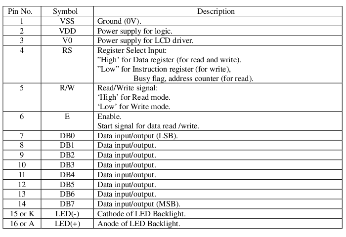 Below
is another pin out of an LCD which has no lighting.
Below
is another pin out of an LCD which has no lighting.
| Pin number |
Symbol |
Level |
I/O |
Function |
| 1 |
Vss |
- |
- |
Power supply (GND) |
| 2 |
Vcc |
- |
- |
Power supply (+5V) |
| 3 |
Vee |
- |
- |
Contrast adjust |
| 4 |
RS |
0/1 |
I |
0 = Instruction input
1 = Data input |
| 5 |
R/W |
0/1 |
I |
0 = Write to LCD module
1 = Read from LCD module |
| 6 |
E |
1, 1->0 |
I |
Enable signal |
| 7 |
DB0 |
0/1 |
I/O |
Data bus line 0 (LSB) |
| 8 |
DB1 |
0/1 |
I/O |
Data bus line 1 |
| 9 |
DB2 |
0/1 |
I/O |
Data bus line 2 |
| 10 |
DB3 |
0/1 |
I/O |
Data bus line 3 |
| 11 |
DB4 |
0/1 |
I/O |
Data bus line 4 |
| 12 |
DB5 |
0/1 |
I/O |
Data bus line 5 |
| 13 |
DB6 |
0/1 |
I/O |
Data bus line 6 |
| 14 |
DB7 |
0/1 |
I/O |
Data bus line 7 (MSB) |
pin1 GND
pin2 VCC usually 5V
pin3 LCD
contrast,
usually uses a potentiometer to properly adjust the contrast
pin4 RS Register Select
0
the
data transferred to the LCD is a command and any data returned
indicates the status
1 the data is
transferred to or from the LCD
pin5 R/W Read/Write
0
write commands or
characters to the LCD
1 read state or characters
from the LCD
pin6 E enable, this
line is used to transfer commands or characters to the LCD.
When
you write on the LCD's acquisition of the LCD is made when this pin
goes from 1 to 0.
When
reading the LCD the acquisition by the MCU must be made after
this
line has gone from 0 to 1, the data remains available until this line
back to 0.
pin7 to pin14 are
the data bus
Remember
that the data can be transferred to 4bit
(nibbles using D4 ... D7) or 8bit.
Instruction
set
Below
are the commands available to drive the LCD
HD44780 instruction set
| Instruction |
Code |
Description |
Execution time** |
| RS |
R/W |
DB7 |
DB6 |
DB5 |
DB4 |
DB3 |
DB2 |
DB1 |
DB0 |
| Clear display |
0 |
0 |
0 |
0 |
0 |
0 |
0 |
0 |
0 |
1 |
Clears display and returns cursor to the home position
(address 0). |
1.64mS |
| Cursor home |
0 |
0 |
0 |
0 |
0 |
0 |
0 |
0 |
1 |
* |
Returns
cursor to home position (address 0). Also returns display being shifted
to the original position. DDRAM contents remains unchanged. |
1.64mS |
| Entry mode set |
0 |
0 |
0 |
0 |
0 |
0 |
0 |
1 |
I/D |
S |
Sets cursor move direction (I/D), specifies to shift
the display (S). These operations are performed during data read/write. |
40uS |
| Display On/Off control |
0 |
0 |
0 |
0 |
0 |
0 |
1 |
D |
C |
B |
Sets On/Off of all display (D), cursor On/Off (C) and
blink of cursor position character (B). |
40uS |
| Cursor/display shift |
0 |
0 |
0 |
0 |
0 |
1 |
S/C |
R/L |
* |
* |
Sets cursor-move or display-shift (S/C), shift
direction (R/L). DDRAM contents remains unchanged. |
40uS |
| Function set |
0 |
0 |
0 |
0 |
1 |
DL |
N |
F |
* |
* |
Sets interface data length (DL), number of display line
(N) and character font(F). |
40uS |
| Set CGRAM address |
0 |
0 |
0 |
1 |
CGRAM address |
Sets the CGRAM address. CGRAM data is sent and received
after this setting. |
40uS |
| Set DDRAM address |
0 |
0 |
1 |
DDRAM address |
Sets the DDRAM address. DDRAM data is sent and received
after this setting. |
40uS |
| Read busy-flag and address counter |
0 |
1 |
BF |
CGRAM / DDRAM
address |
Reads
Busy-flag (BF) indicating internal operation is being performed and
reads CGRAM or DDRAM address counter contents (depending on previous
instruction). |
0uS |
| Write to CGRAM or DDRAM |
1 |
0 |
write data |
Writes data to CGRAM or DDRAM. |
40uS |
| Read from CGRAM or DDRAM |
1 |
1 |
read data |
Reads data from CGRAM or DDRAM. |
40uS |
Remarks:
- DDRAM = Display
Data RAM.
- CGRAM = Character
Generator RAM.
- DDRAM address
corresponds to cursor position.
- * = Don't care.
- ** = Based on Fosc = 250kHz.
Bit names
| Bit name |
Setting
/ Status |
| I/D |
0 = Decrement cursor position |
1 = Increment cursor position |
| S |
0 = No display shift |
1 = Display shift |
| D |
0 = Display off |
1 = Display on |
| C |
0 = Cursor off |
1 = Cursor on |
| B |
0 = Cursor blink off |
1 = Cursor blink on |
| S/C |
0 = Move cursor |
1 = Shift display |
| R/L |
0 = Shift left |
1 = Shift right |
| DL |
0 = 4-bit interface |
1 = 8-bit interface |
| N |
0 = 1/8 or 1/11 Duty (1 line) |
1 = 1/16 Duty (2 lines) |
| F |
0 = 5x7 dots |
1 = 5x10 dots |
| BF |
0 = Can accept instruction |
1 = Internal operation in progress |
In
generale un LCD di 2 righe per 40 caratteri sarà come sotto.
 Interfacing
The
LCD can be interfaced to 8 and 4 bits.
8-bit interface
Interfacing
The
LCD can be interfaced to 8 and 4 bits.
8-bit interface
Example
of busy flag
testing using an 8-bit interface.

4-bit
interface
Example of busy
flag testing using a 4-bit interface.
 Example of data transfer using a 4-bit interface.
 Character
set
Below
are sample CGROM Character Code Table of MDLS16265BLVLD4
Character
set
Below
are sample CGROM Character Code Table of MDLS16265BLVLD4
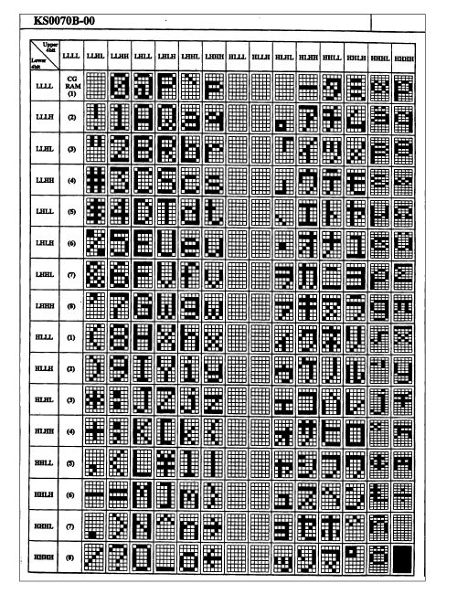 Under
there is a map of another character LCD with font size 5x7 dots
Under
there is a map of another character LCD with font size 5x7 dots
 SOFTWARE
To
develop a suitable set of commands for the LCD must provide at least
the commands below:
SOFTWARE
To
develop a suitable set of commands for the LCD must provide at least
the commands below:
LCD
initialisation
Entry mode
- Sets entry mode of the LCD
- b0 : 0 = no display shift, 1 = display shift
 b1 : 0 = auto-decrement, 1 = auto-increment
 b2-b7 : don't care
Display
mode
- Sets display control
- b0 : 0 = cursor blink off, 1 = cursor blink on (if b1 = 1)
 b1 : 0 = cursor off, 1 = cursor on
 b2 : 0 = display off, 1 = display on (display data remains in DD-RAM)
 b3-b7 : don't care
Set
character generator RAM address
- Sets the Character-Generator-RAM address.
 CGRAM data is read/written after this setting.
Set
display data RAM address
- Sets the Display-Data-RAM address.
 DDRAM data is read/written after this setting.
Get
address counter contents
- Returns address counter contents, used for both DDRAM and CGRAM.
Test
Busy flag
Clear
display
Clear
Line(num.line)
Cursor
home
Set
cursor position(row, position)
Write
character
Write
string