RS485

ZL
- line impedance
Zo
- cable impedance
A
(-)
e B
(+)
- names of the RS485 lines
twisted-pair
- pairs of wires twisted together
AWG
- number that indicates the characteristics of the electric wire, AWG24: is the classic telephon wire
STBx
- duration of each transmitted bit
Tp
- is time that the signal takes to travel the bus 485
Introduction
The bus 485 is generally formed by a cable (twisted-pair) plus a shielding, which connects the various devices, see Fig.3.
A bus consists of two wires is called: half-duplex.
A bus consists of four wires is called: full-duplex.
A
good bus 485 is achieved by remaining between 400 and 500m maximum
length. Obviously, reducing the bus speed can also reach 1200m.
Because
the modules are connected on the network are also influenced
significantly by the mass differences that are created, especially on
networks very long, you should use the couplers electrically isolated.
The transmission of the signal is called differential, that are the result of the difference between the voltages of the two wires that make up the bus Fig.0
Fig.0
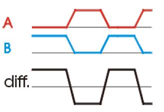
The transmitters 485 provide (under load), an output level of ± 2 V between outputs A and B, the receivers recognize levels of ± 200 mV even as a valid signal.
This technique provides excellent noise immunity even on very long cable.
Typically, the section of cable can be 24 or 22 AWG for medium distances, and must be increased in case of long distances.
To minimize reflections, the first and last device in the network
must have a terminator resistor connected in parallel to the line.
The
above statement is not true if the line is made a star for which the
position of the terminating resistor will be tested experimentally.
In
this network, which are very rare, you put a termination resistor on
the center star and the second resistance on the node farther from the
star center.
The standard RS485 can theoretically support up to 32 devices
connected on the bus (with the modern 485 you arrive safely at 128
knots and some 485 special and so expensive to get up to 256 knots).
Typically
you need to use terminating resistors whose value varies from 120 to
560 ohms, see below explanations on how to choose termination resistors.
Capacitive load, resistive load and inductive load: on the line
With
long cables must take into account the capacity (C), resistance (R) and
inductance (L) of the cable. RLC are dominant factor in power
consumption and generate signal reflections.
Capacitance, inductance and resistance are expressed in linear meters and this data are found in the data sheet of the cables.
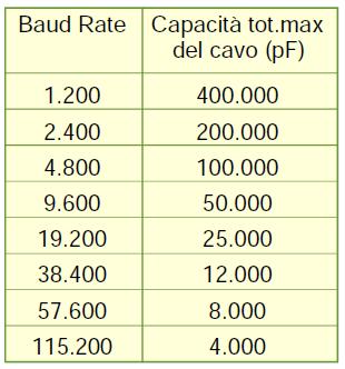
The cable capacitance (in pF/m) is typically between 50pF/mt (for good quality cables, eg. cable Cat 5) and 100pF/mt.
In case of doubt or especially with very long lines is preferable to choose cable with large sections (0,5...1mm).
The table in Figure 1 can be a useful guide for assessing the link between distance and speed.
Fig.1
According to the standard RS485 the line connections are indicated by:
B also called B + (plus)
GND
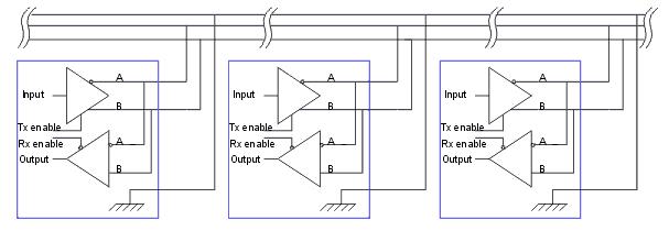
All devices connected on the line must be connected in parallel Fig.2, half-duplex:
Fig.2
A typical network 485 may be wired as shown in Fig.3:
Fig.3
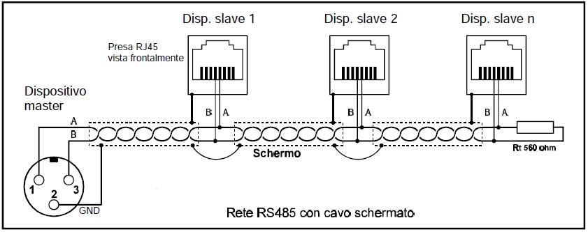
It is very important that the wiring is done with twisted cable that provides maximum noise immunity.
It is also possible use an unshielded cable, while reducing network speed.
Impedance matching
To obtain a transmission line as possible immune to the noise , (the
noise that typically occurs on a transmission line is the reflection of
the transmitted signal that causes interference will not negligible), it is a good idea to keep the line impedance balanced, is that's why we use the impedance matching.
Impedance adapters are one or two resistors placed at one end of the line or on both ends of the line.
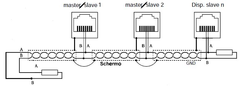
Next, Fig.4 and Fig.5, shows two cases.
Fig.4
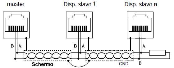
Fig.5
Termination resistors
To understand if is it necessary put the transmission line terminators, is possible use the following parameter:
If the duration of a single bit transmitted (SBTx) is greater than at least 10 times the time (Tp) that the signal takes to travel down the line termination is not needed.
Line terminations are not needed if: SBTx
> ( 10 * Tp )
To understand how to make these assessments using numbers is necessary remember that:
2) each cable is characterized by specific parameters such as capacitance, inductance, resistance can be summarized in impedance Zo of the cable
We do a practical example:
2) network length: 1200 m
With these parameters, the propagation time signal is:
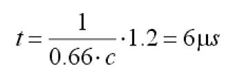
9600
baud == 9600 bit/sec, the time of the individual bits is:
Returning to the formula SBTx
> ( 10 * t ) we have that:
104,166 > 60
In this case is not necessary use the line termination.
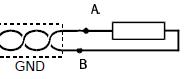
Se invece fosse necessario terminare la linea quello che si fa è mettere sul nodo più lontano dal master una resistenza a carbone collegata tra A e B il cui valore deve essere pari all'impedenza caratteristica della linea ZL.
If is necessary insert the line termnation,
In Fig.6, there is an example typical of termination.
The problem is to determine correctly the impedance ZL which is connected to the cable impedance Zo and to the chip 485 impedance .
In general the impedance ZL varies between 120 and 560 ohms, but with the modern 485 you get also a 10 ... 12 Kohm.
Fig.6
ATTENTION: the line termination resistors increase the consumption of the bus 485.
If we suppose to insert a single 120 ohm termination resistor and the differential voltage on the 5V, we have the current in the bus will be:
41mA = 5 / 120.
Capacity and resistors termination
To decrease the current flowing in the line (battery-powered applications), we use a resistive capacitive termination, Fig.7, whose value is calculated as follows:
C = Tp / ZL
Tp
- time the signal takes to travel across the bus 485
Fig.7
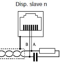
Eye Diagram
To
evaluate the physical quality of the signal on the bus we can use an
oscilloscope with differential input to see the eye diagram Fig.8.
For see the ey is necessary an
oscilloscope with differential inputs, with the trigger set to the
threshold of discrimination between 0 and 1 and the time base
coinciding with two or three bits of transmission.
In Fig.8 the signal is OK on the left but on the right the signal is impossible do detect.
Fig.8
Polarization of the bus 485
If
the bus 485 is multi-master or otherwise when no one that "speaks" the
line is left in high impedance, all the RS485 in receive mode, the
problem arises of the polarization of the bus.
The
bus in high impedance cud picks up electromagnetic interference from
the outside that can be interpreted as real signals from the receivers.
To resolve this problem there are two ways:
2) Polarize the bus as Fig.9 (fail-safe)
Fig.9
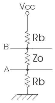
Wanting to use the solution Fig.9 keep in mind that the resistance Rb must maintain a value between A and B of 200mV when all 485 are in Rx mode.
We make an example to understand how to find the numerical value of Rb.
Suppose we have the following conditions:
Bus consists of 32 nodes with input impedance of 12K
Two termination resistors to 120ohm
Supply voltage 5V
The overall resistance between lines A and B will be: 120//120//(32
x 12K) approximately 52ohm
To have a voltage between A and B of 200mV with 52ohm it is necessary to circulate a current of about 4mA.
The two resistors Rb must be each:
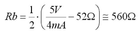
This bias network must be placed in a single place in the network.
CAUTION: Many of 485 latest generation have already integrated these resistors, so it becomes unnecessary to put them outside.
Surge Protection
In general it is good practice to provide some surge protection system especially if the bus is very long.
Some devices that are typically used for surge protection are MOV, TRANZORB and Gas Discharge.
These
devices must have operating voltage from 8 to 10V and parasitic
capacitance as small as possible especially if the bus 485 is a high
speed.
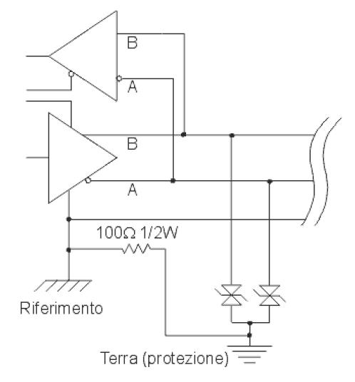
In Fig.10 shows a typical diagram.
Fig.10
Home
MCU & Peripheral