SPI
Serial Peripheral Interface
Serial Peripheral Interface
SPI
is a serial synchronous protocol that allows a master device to
initiate communication with a slave device.
SPI is a Master-Slave protocol.
SPI protocol use the 4 line below.
SS - This signal is known as Slave Select. When it goes low, the slave device will listen for SPI clock and data signals.
Alternative naming conventions are also widely used:
nCS, CS, nSS, STE — Chip Select, Slave Transmit Enable (active low; output from master)
SCK - This is the serial clock signal. It is generated by the master device and controls when data is sent and when it is read.
Alternative naming conventions are also widely used:
CLK — Serial Clock (output from master)
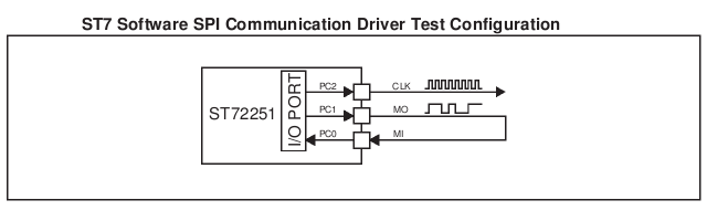
SDO - This is the Serial Data Output signal.
Alternative naming conventions are also widely used:
MO - Master Output data line or
MOSI - Master Output Slave Input data line
DO, SO — Data Out, Serial Out
SDI - This is the Serial Data Input line.
Alternative naming conventions are also widely used:
MI - Master Input data line or
MISO - Master Input Slave Output data line
DI, SI — Data In, Serial In
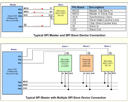
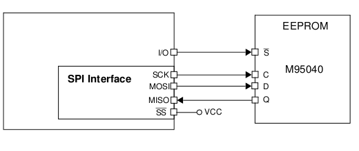
Typical connection:
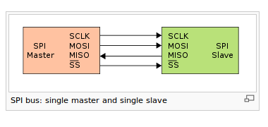
SPI is a Master-Slave protocol.
SPI protocol use the 4 line below.
SS - This signal is known as Slave Select. When it goes low, the slave device will listen for SPI clock and data signals.
Alternative naming conventions are also widely used:
nCS, CS, nSS, STE — Chip Select, Slave Transmit Enable (active low; output from master)
SCK - This is the serial clock signal. It is generated by the master device and controls when data is sent and when it is read.
Alternative naming conventions are also widely used:
CLK — Serial Clock (output from master)
SDO - This is the Serial Data Output signal.
Alternative naming conventions are also widely used:
MO - Master Output data line or
MOSI - Master Output Slave Input data line
DO, SO — Data Out, Serial Out
SDI - This is the Serial Data Input line.
Alternative naming conventions are also widely used:
MI - Master Input data line or
MISO - Master Input Slave Output data line
DI, SI — Data In, Serial In
Typical connection:
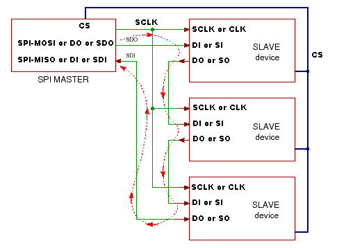
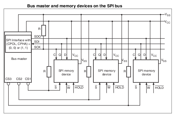
SPI Daisy Chain
Data Transmission
To begin a communication, the master first configures the clock, using a frequency less than or equal to the maximum frequency the slave device supports. Such frequencies are commonly in the range of 1-70 MHz.
The master then pulls the SS
(slave select) low for the desired chip.
If
a waiting period is required (such as for
analog-to-digital conversion)
then the master must wait
for at least that period of time before
starting to issue clock cycles.
During each SPI
clock cycle, a full duplex data transmission occurs:
- the master sends a bit on the MOSI line
the slave reads it from the MISO line - the slave sends a bit on the MISO line
the master reads it from the MOSI line
SCK clock signal is provided by the master
to provide synchronization.
Only the master device can control the clock line, SCK.
No data will be transferred unless the clock is manipulated.
The clock signal controls when data can change and when it is valid for reading.
Since SPI is synchronous, it has a clock pulse along with the data.
Since SPI has a clock signal, the clock can vary without disrupting the data.
The data rate will simply change along with the changes in the clock rate.
This makes SPI ideal when the microcontroller is being clocked imprecisely, such as by a RC oscillator.
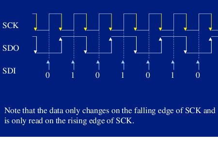
Normaly the transmitted data change during the falling edge (transaction 1 to 0) and the receive get data during the rising edge (transaction 0 to 1).
Some devices use a sequence reverse to that described above.
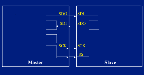
Here is an example of SPI communication.
Often a Slave Select signal (SS) will control when a device is accessed.
This signal must be used for when more than one slave exists in a system, but can be optional when only one slave exists in the circuit.
As a general rule, it should be used.
SS indicates to a slave that the master wishes to start an SPI data exchange between that slave device and itself.
The signal is most often active low, so a low on this line will indicate the SPI is active, while a high will signal inactivity.
It is often used to improve noise immunity of the system. Its function is to reset the SPI slave so that it is ready to receive the next byte.
Only the master device can control the clock line, SCK.
No data will be transferred unless the clock is manipulated.
The clock signal controls when data can change and when it is valid for reading.
Since SPI is synchronous, it has a clock pulse along with the data.
Since SPI has a clock signal, the clock can vary without disrupting the data.
The data rate will simply change along with the changes in the clock rate.
This makes SPI ideal when the microcontroller is being clocked imprecisely, such as by a RC oscillator.
Normaly the transmitted data change during the falling edge (transaction 1 to 0) and the receive get data during the rising edge (transaction 0 to 1).
Some devices use a sequence reverse to that described above.
Here is an example of SPI communication.
Often a Slave Select signal (SS) will control when a device is accessed.
This signal must be used for when more than one slave exists in a system, but can be optional when only one slave exists in the circuit.
As a general rule, it should be used.
SS indicates to a slave that the master wishes to start an SPI data exchange between that slave device and itself.
The signal is most often active low, so a low on this line will indicate the SPI is active, while a high will signal inactivity.
It is often used to improve noise immunity of the system. Its function is to reset the SPI slave so that it is ready to receive the next byte.