
Home
Page
STM32 Page
STM32 Tutorials
INDEX
STM32 Page
STM32 Tutorials
INDEX
STM32 Library global view
File inclusion relationship
Supported toolchains
Package description
Coding conventions
Code example
File inclusion relationship
Supported toolchains
Package description
Coding conventions
Code example
Please read also this:
.
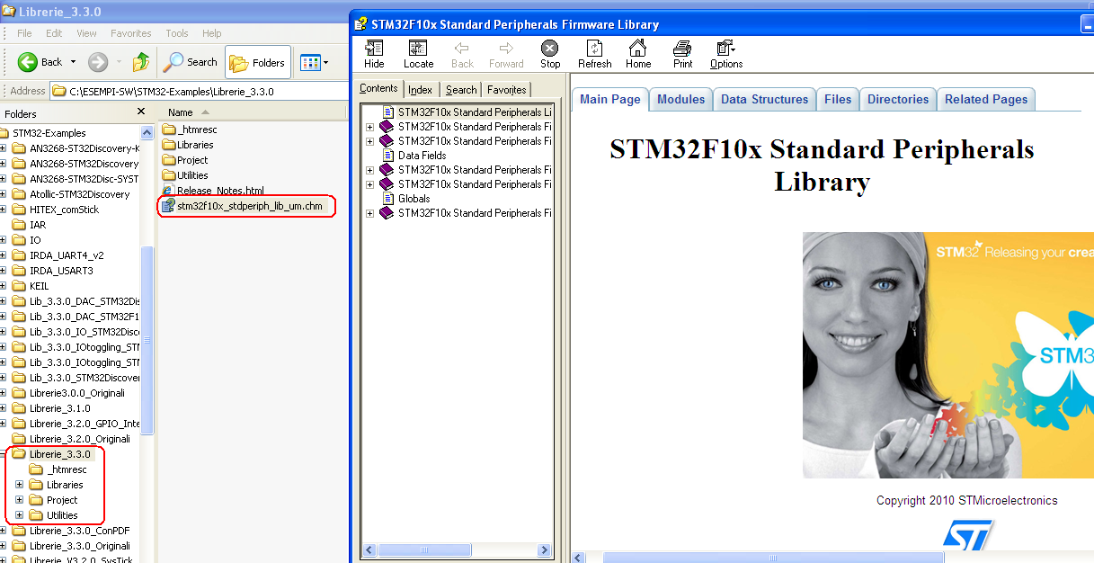
The documentation file is generated in automatic by using DOXYGEN.
This is convenient to maintain up to date the documentation but is not easy find the topics inside the documentation and to understand the way to use the library.
The file of documentation is: stm32f10x_stdperiph_lib um.chm (see below).
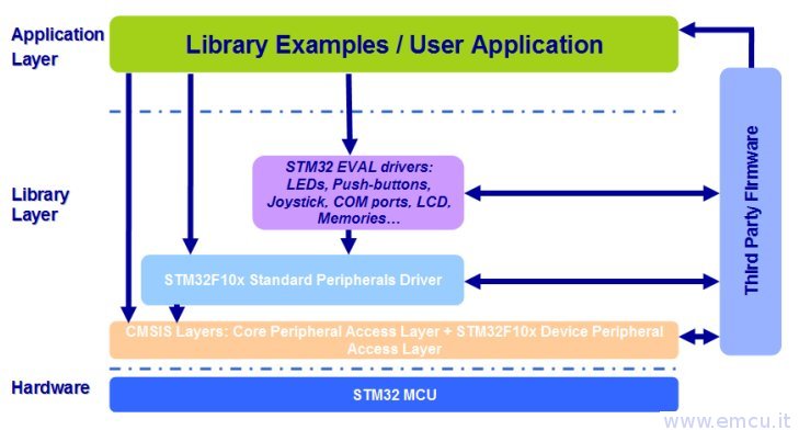
The following figure provides a global view of the STM32F10x Standard Peripherals Library usage and interaction with other firmware conponents.
The Standard Peripherals library file inclusions relationship is shown in the following figure:
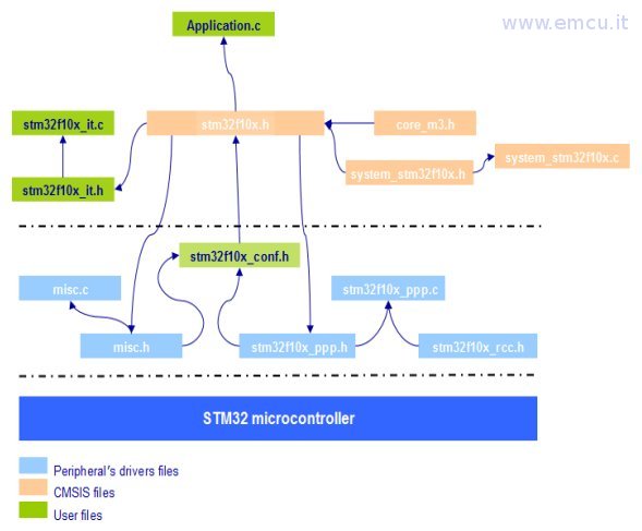
The stm32f10x_ppp.c file contains all the firmware functions required to use the PPP peripheral.
A single memory mapping file, stm32f10x.h, is supplied for all peripherals.
It contains all the register declarations and bits definition.
This is the only file that needs to be included in the user application to interface with the library.
The stm32f10x_conf.h file is used to specify the set of parameters to interface with the library drivers before running any application.
Supported toolchains
The Standard Peripherals Library supports the following toolchains:
- KEIL - RealView Microcontroller Development Kit MDK-ARM
- IAR - Embedded Workbench for ARM EWARM
- Raisonance Integrated Development Environment RIDE7
- Hitex Development Tools HiTOP
- Atolic TrueSTUDIO
Package description
The STM32F10x Standard Peripherals library is supplied in one single zip file.
The extraction of the zip file generates one folder, STM32F10x_StdPeriph_Lib_VX.Y.Z, which contains the following subfolders:
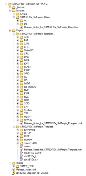
_htmresc folder
The extraction of the zip file generates one folder, STM32F10x_StdPeriph_Lib_VX.Y.Z, which contains the following subfolders:
_htmresc folder
This Folder contains all package html page resources.
Libraries folder
This folder contains all CMSIS files and STM32F10x Standard Peripheral's Drivers.
This folder contains all CMSIS files and STM32F10x Standard Peripheral's Drivers.
CMSIS subfolder
This folder contains the STM32F10xxx CMSIS files: device peripheral access layer and core peripheral access layer
STM32F10x_StdPeriph_Driver subfolderThis folder contains all the subdirectories and files that make up the core of the library:
inc sub-folder contains the Peripheral's Drivers header files. They do not need to be modified by the user.
src sub-folder contains the Peripheral's Drivers source files. They do not need to be modified by the user.
All STM32F10x Standard Peripheral's drivers are coded in Strict ANSI-C and are independent from the software toolchain.
Project folder
This folder contains template projects and STM32F10x Standard Peripheral's examples.
STM32F10x_StdPeriph_Examples subfolder
This
folder contains, for each peripheral sub-folder, the minimum set of
files needed to run a typical example on how to use this peripheral:
readme.txt: brief text file describing the example and how to make it work.
stm32f10x_conf.h: header file allowing to enable/disable the peripheral's drivers header files inclusion.
stm32f10x_it.c: source file containing the interrupt handlers (the function bodies may be emptied if not used).
stm32f10x_it.h: header file including all interrupt handler prototypes.
main.c: example of code.
platform_config.h: (if exists) STMicroelectronics Evaluation board specific configuration file.
STM32F10x_StdPeriph_Template subfolderreadme.txt: brief text file describing the example and how to make it work.
stm32f10x_conf.h: header file allowing to enable/disable the peripheral's drivers header files inclusion.
stm32f10x_it.c: source file containing the interrupt handlers (the function bodies may be emptied if not used).
stm32f10x_it.h: header file including all interrupt handler prototypes.
main.c: example of code.
platform_config.h: (if exists) STMicroelectronics Evaluation board specific configuration file.
This
folder contains standard template projects for EWARMv5, MDK-ARM, RIDE,
HiTO and TrueSTUDIO toolchains that compile the needed.
STM32F10x Standard Peripheral's drivers plus all the user-modifiable files that are necessary to create a new project:
stm32f10x_conf.h: configuration header file.
stm32f10x_it.c: source file containing the interrupt handlers (the function bodies are empty in this template).
stm32f10x_it.h: header file including all interrupt handlers prototypes.
main.c: main program body.
EWARMv5, MDK-ARM, RIDE, HiTOP subfolders:
contains
respectively the template project for EWARMv5, MDK-ARM, RIDE, HiTOP and
TrueSTUDIO toolchains (for more details, refer to readme file provided
within the template project).
Two workspaces are provided for each project template:
- STM32100B-EVAL: to configure the project for STM32 Medium-density Value line devices
- STM3210C-EVAL: to configure the project for STM32 Connectivity line devices
- STM3210E-EVAL: to configure the project for STM32 High-density devices
- STM3210B-EVAL: to configure the project for STM32 Medium-density devices
- STM32F10X_XL: to configure the project for STM32 XL-density devices
Utilities folder
STM32_EVAL
Implement an abstraction layer to interact with the Human Interface
resources; buttons, LEDs, LCD and COM ports (USARTs)
available on STMicroelectronics STM32100B-EVAL (Medium-density Value line), STMicroelectronics STM3210C-EVAL (Connectivity line),
STM3210E-EVAL (High-density and XL-density) and STM3210B-EVAL (Medium-density) evaluation boards.
The stm32_eval.c driver provides a common API to interact with buttons, LEDs and COM ports, while these resources hardware definitions is made in the header file of each evaluation board (stm3210x_eval.h). A common API is provided to manage the LCD across the supported boards, with a separate driver for each board stm3210x_eval_lcd.c.
Common: contains common part for all STM32 EVAL board containing: Leds, push-buttons, COM ports, serial I2C EEPROM
memory (sEE), serial SPI FLASH memory (sFLASH), Temperature sensor (LM75), SD Card memories on SPI and SDIO interfaces.
STM32100B_EVAL: contains LEDs, buttons and COM ports hardware definition file, LCD driver and HDMI CEC driver for this board.
STM3210C_EVAL: contains LEDs, buttons and COM ports hardware definition file, IO Expander and LCD driver for this board.
STM3210E_EVAL: contains LEDs, buttons and COM ports hardware definition file, LCD driver, FSMC SRAM driver, FSMC NOR driver and FSMC NAND driver for this board.
STM3210B_EVAL: contains LEDs, buttons and COM ports hardware definition file and LCD driver for this board.
Coding Conventions
All firmware is coded in ANSI-C
PPP is used to reference any peripheral acronym, e.g. TIM for Timer.
Registers & Structures
Common files (map/lib/type) have to be included to the working directory project
To use the peripheral PPPx
If you want to debug your application, you have to define the label DEBUG in the stm32f10x_conf.h file :
Include this line in your application source code :
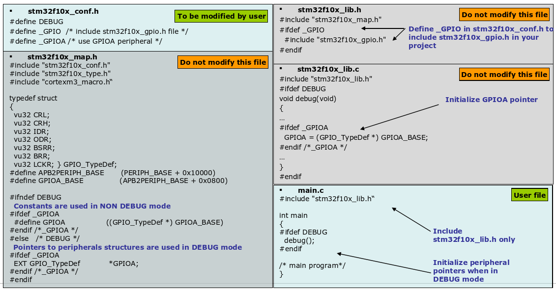
In the main file , you have to declare a PPP_InitTypeDef structure, e.g:
Strict ANSI-C for all library peripheral files
Relaxed ANSI-C for projects & Examples files.
PPP is used to reference any peripheral acronym, e.g. TIM for Timer.
Registers & Structures
STM32F10x registers are mapped in the microcontroller address space
FW library registers have the same names as in STM32F10x Datasheet & reference manual.
All registers hardware accesses are performed through a C structures :Work with only one base address and indirect addressing
Improve code re-use : e.g. the same structure to handle and initialize 3 USARTs.
Improve code re-use : e.g. the same structure to handle and initialize 3 USARTs.
Common files (map/lib/type) have to be included to the working directory project
To use the peripheral PPPx
stm32f10x_ppp.c and stm32f10x_ppp.h files must be included to the working project
Edit the stm32f10x_conf.h file and uncomment the following lines relatetd to the peripheral that you need to use:
Edit the stm32f10x_conf.h file and uncomment the following lines relatetd to the peripheral that you need to use:
#define _PPP (mandatory)
#define _PPPx (optional, depending on the peripheral)
#define _PPPx (optional, depending on the peripheral)
If you want to debug your application, you have to define the label DEBUG in the stm32f10x_conf.h file :
#define DEBUG
This creates a pointer, in memory, to the peripheral structure, so debug become easier and dumping a peripheral variable provides all registers settings.
This creates a pointer, in memory, to the peripheral structure, so debug become easier and dumping a peripheral variable provides all registers settings.
Include this line in your application source code :
#include “stm32f10x_lib.h”
In the main file , you have to declare a PPP_InitTypeDef structure, e.g:
GPIO_InitTypeDef GPIO_InitStructure;
The PPP_InitStructure is a working variable located in data memory that allows you to initialize one or more instance of PPPs.
You have to fill the PPP_InitStructure variable with the allowed values of the structure member.PPP_InitStructure.member1 = val1;
PPP_InitStructure.member2 = val2;
...
PPP_InitStructure.memberN = valN;
You have to initialize the PPP peripheral by calling the PPP_Init(..) function :PPP_InitStructure.member2 = val2;
...
PPP_InitStructure.memberN = valN;
PPP_Init(PPPx, &PPP_InitStructure);
At this stage the PPP peripheral is initialized and can be enabled by making a call to PPP_Cmd(..) function.PPP_Cmd(PPPx, ENABLE);
Example:
// Configure SPI
SPI_InitStructure.SPI_Direction = SPI_Direction_2Lines_FullDuplex;
SPI_InitStructure.SPI_Mode = SPI_Mode_Master;
SPI_InitStructure.SPI_DataSize = SPI_DataSize_8b;
SPI_InitStructure.SPI_CPOL = SPI_CPOL_High;
SPI_InitStructure.SPI_CPHA = SPI_CPHA_2Edge;
SPI_InitStructure.SPI_NSS = SPI_NSS_Soft;
SPI_InitStructure.SPI_BaudRatePrescaler = SPI_BaudRatePrescaler_64;
SPI_InitStructure.SPI_FirstBit = SPI_FirstBit_MSB;
SPI_InitStructure.SPI_CRCPolynomial = 7;
SPI_Init(SPI1, &SPI_InitStructure);
SPI_Cmd(SPI1, ENABLE);
To access the functionality of the PPP peripheral, the user can use a set of dedicated functions.
These functions are specific to the peripheral and for more details refer to STM32F10x Firmware Library User Manual.
Notes :
1) Before configuring a peripheral, you have to enable its clock by calling one of the following functions:
Exampe:
RCC_AHBPeriphClockCmd(RCC_AHBPeriph_PPPx , ENABLE);
RCC_APB2PeriphClockCmd(RCC_APB2Periph_PPPx , ENABLE);
RCC_APB1PeriphClockCmd(RCC_APB1Periph_PPPx , ENABLE);
2) PPP_DeInit(..) function can be used to set all PPP’s peripheral registers to their reset values:RCC_APB2PeriphClockCmd(RCC_APB2Periph_PPPx , ENABLE);
RCC_APB1PeriphClockCmd(RCC_APB1Periph_PPPx , ENABLE);
PPP_DeInit(PPPx);
3) If after peripheral configuration, the user wants to modify one or more peripheral settings he should proceed as following: PPP_InitStucture.memberX = valX;
PPP_InitStructure.memberY = valY;
PPP_Init(PPPx, &PPP_InitStructure);
PPP_InitStructure.memberY = valY;
PPP_Init(PPPx, &PPP_InitStructure);
Exampe:
// Enable CLK to port ADC1, GPIOC/A, USART1, SPI1
RCC_APB2PeriphClockCmd(RCC_APB2Periph_ADC1 | RCC_APB2Periph_GPIOC | RCC_APB2Periph_GPIOA | RCC_APB2Periph_USART1
| RCC_APB2Periph_SPI1, ENABLE);
/* Enable DMA1 clock */
RCC_AHBPeriphClockCmd(RCC_AHBPeriph_DMA1, ENABLE);
/* Fills the RCC_ClockFreq structure with the current frequencies of different on chip clocks (for debug purpose) */
RCC_GetClocksFreq(&RCC_ClockFreq);
Code example
/**
Date: April 2011
Author: Enrico Marinoni
MCU: STM32F100RBT6B
EvaBoard: STM32FVL Discovery
http://www.emcu.it/STM32Discovery/STM32ValueLineDiscovery.html
STM Library Version: V3.4.0
KEIL Version: uVision4
IDE-Version: µVision V4.10
Toolchain: RealView MDK-ARM Version: 4.12
Toolchain Path: BIN40\
C Compiler: Armcc.Exe V4.1.0.481 [Evaluation]
Assembler: Armasm.Exe V4.1.0.481 [Evaluation]
Linker/Locator: ArmLink.Exe V4.1.0.481 [Evaluation]
Librarian: ArmAr.Exe V4.1.0.481 [Evaluation]
Hex Converter: FromElf.Exe V4.1.0.481 [Evaluation]
CPU DLL: SARMCM3.DLL V4.12
Dialog DLL: DARMSTM.DLL V1.47
Target DLL: STLink\ST-LINKIII-KEIL.dll V1.5.1
Dialog DLL: TARMSTM.DLL V1.47
Software Description:
Configure SYSCLK (System clock) to 24Mhz
Send to the MCO (PA8) the SYSCLK
Configure LD3 & LD4 (Led)
LD4 flashes according with ADC measure
ADC (used on ADC1_IN10 pin PC0) in DMA mode that determines the speed of LD4 flashing
Push Button-BLUE (B1 USER) if is press the LD3 go ON
USART1 is configure to send the status of Push Button-BLUE (B1 USER - see the variable: RxChar)
The USART1 SetUp is:
USART1 used in UART1 mode
BaudRate 9600
WordLength_8b
StopBits_1
Parity_No
FlowControl_None
SPI1 (used on PA5 (CLK), PA6 (MISO), PA7 (MOSI).
SPI is configure to send the status of Push Button-BLUE (B1 USER - see the variable: SPI1val)
*
* THE PRESENT FIRMWARE WHICH IS FOR GUIDANCE ONLY AIMS AT PROVIDING CUSTOMERS
* WITH CODING INFORMATION REGARDING THEIR PRODUCTS IN ORDER FOR THEM TO SAVE
* TIME. AS A RESULT, STMICROELECTRONICS SHALL NOT BE HELD LIABLE FOR ANY
* DIRECT, INDIRECT OR CONSEQUENTIAL DAMAGES WITH RESPECT TO ANY CLAIMS ARISING
* FROM THE CONTENT OF SUCH FIRMWARE AND/OR THE USE MADE BY CUSTOMERS OF THE
* CODING INFORMATION CONTAINED HEREIN IN CONNECTION WITH THEIR PRODUCTS.
*
*/
/* Includes ------------------------------------------------------------------*/
#include "stm32f10x.h"
#include "stdio.h"
/* Private typedef -----------------------------------------------------------*/
/* Private define ------------------------------------------------------------*/
#define ADC1_DR_Address ((uint32_t)0x4001244C) // Used for ADC
/* Private macro -------------------------------------------------------------*/
/* Private variables ---------------------------------------------------------*/
GPIO_InitTypeDef GPIO_InitStructure;
RCC_ClocksTypeDef RCC_ClockFreq;
ErrorStatus HSEStartUpStatus;
ADC_InitTypeDef ADC_InitStructure; // Used for ADC
DMA_InitTypeDef DMA_InitStructure; // Used for ADC
__IO uint16_t ADCConvertedValue; // Used for ADC
USART_InitTypeDef USART_InitStructure; // Used for USART
u8 RxChar=0x0; // Used for USART
SPI_InitTypeDef SPI_InitStructure; // Used for SPI
u16 SPI1val; // Used for SPI
/* Private function prototypes -----------------------------------------------*/
void Delay(__IO uint32_t nCount);
void SetSysClockTo24(void); // Configure System Clock to HSE at 24MHz (external 8MHz crystal)
void EnableCLK(void); // Enable CLK to PORTs and Peripherals
void GPIO_Configuration(void); // Configure the I/O
void ConfigureDMAforADC(void); // Configure DMA for ADC
void NVIC_Configuration(void); // Used for USART
void ConfigureUART1(void); // Used for USART
void ConfigureSPI1(void); // Used for SPI
/* Private functions ---------------------------------------------------------*/
int main(void)
{
/* Setup the microcontroller system. Initialize the Embedded Flash Interface,
initialize the PLL and update the SystemFrequency variable. */
SystemInit();
// Sets System clock frequency to 24MHz
SetSysClockTo24();
// Enable CLK to PORTs and Peripherals
EnableCLK();
// Configure the I/O
GPIO_Configuration();
// Configure DMA for ADC
ConfigureDMAforADC();
// Configure USART1
ConfigureUART1();
// Configure SPI
ConfigureSPI1();
while (1)
{
/* Turn on LD4 - PC8 */
GPIO_SetBits ( GPIOC, GPIO_Pin_8 );
/* Insert delay */
Delay(ADCConvertedValue*100);
/* Turn off LD4 - PC8 */
GPIO_ResetBits ( GPIOC, GPIO_Pin_8 );
/* Insert delay */
Delay(ADCConvertedValue*100);
// Read BLUE Botton
if(!GPIO_ReadInputDataBit(GPIOA, GPIO_Pin_0))
{
GPIO_ResetBits ( GPIOC, GPIO_Pin_9 );
USART_SendData(USART1, '1');
SPI_I2S_SendData (SPI1, 0x1);
}
else
{
GPIO_SetBits ( GPIOC, GPIO_Pin_9 );
USART_SendData(USART1, '0');
SPI_I2S_SendData (SPI1, 0x0);
}
// Read SPI1
SPI1val=SPI_I2S_ReceiveData(SPI1);
}
}
// +++++++++ SetUp +++++++++++++++++++++++++++++++++++++++++++
void Delay(__IO uint32_t nCount)
{
for(; nCount != 0; nCount--);
}
//
// Configure SPI
//
void ConfigureSPI1(void)
{
SPI_InitStructure.SPI_Direction = SPI_Direction_2Lines_FullDuplex;
SPI_InitStructure.SPI_Mode = SPI_Mode_Master;
SPI_InitStructure.SPI_DataSize = SPI_DataSize_8b;
SPI_InitStructure.SPI_CPOL = SPI_CPOL_High;
SPI_InitStructure.SPI_CPHA = SPI_CPHA_2Edge;
SPI_InitStructure.SPI_NSS = SPI_NSS_Soft;
SPI_InitStructure.SPI_BaudRatePrescaler = SPI_BaudRatePrescaler_64;
SPI_InitStructure.SPI_FirstBit = SPI_FirstBit_MSB;
SPI_InitStructure.SPI_CRCPolynomial = 7;
SPI_Init(SPI1, &SPI_InitStructure);
SPI_Cmd(SPI1, ENABLE); /* Enable the SPI */
}
//
// Configure UART1
//
void ConfigureUART1(void)
{
/* USART1 configured as follow:
- BaudRate = 9600 baud
- Word Length = 8 Bits
- ONE Stop Bit
- NO parity
- Hardware flow control disabled (RTS and CTS signals)
- Receive and transmit enabled
*/
USART_InitStructure.USART_BaudRate = 9600;
USART_InitStructure.USART_WordLength = USART_WordLength_8b;
USART_InitStructure.USART_StopBits = USART_StopBits_1;
USART_InitStructure.USART_Parity = USART_Parity_No;
USART_InitStructure.USART_HardwareFlowControl = USART_HardwareFlowControl_None;
USART_InitStructure.USART_Mode = USART_Mode_Rx | USART_Mode_Tx;
USART_Init(USART1, &USART_InitStructure); // Configure the USART1
/* Enable the USART Transmit interrupt: this interrupt is generated when the
USART1 transmit data register is empty */
USART_ITConfig(USART1, USART_IT_TXE, ENABLE);
/* Enable the USART Receive interrupt: this interrupt is generated when the
USART1 receive data register is not empty */
USART_ITConfig(USART1, USART_IT_RXNE, ENABLE);
/* Enable USART1 */
USART_Cmd(USART1, ENABLE);
}
//
// Configure DMA for ADC
//
void ConfigureDMAforADC(void)
{
/* DMA1 channel1 configuration ----------------------------------------------*/
DMA_DeInit(DMA1_Channel1);
DMA_InitStructure.DMA_PeripheralBaseAddr = ADC1_DR_Address;
DMA_InitStructure.DMA_MemoryBaseAddr = (uint32_t)&ADCConvertedValue;
DMA_InitStructure.DMA_DIR = DMA_DIR_PeripheralSRC;
DMA_InitStructure.DMA_BufferSize = 1;
DMA_InitStructure.DMA_PeripheralInc = DMA_PeripheralInc_Disable;
DMA_InitStructure.DMA_MemoryInc = DMA_MemoryInc_Disable;
DMA_InitStructure.DMA_PeripheralDataSize = DMA_PeripheralDataSize_HalfWord;
DMA_InitStructure.DMA_MemoryDataSize = DMA_MemoryDataSize_HalfWord;
DMA_InitStructure.DMA_Mode = DMA_Mode_Circular;
DMA_InitStructure.DMA_Priority = DMA_Priority_High;
DMA_InitStructure.DMA_M2M = DMA_M2M_Disable;
DMA_Init(DMA1_Channel1, &DMA_InitStructure);
/* Enable DMA1 channel1 */
DMA_Cmd(DMA1_Channel1, ENABLE);
/* ADC1 configuration ------------------------------------------------------*/
ADC_InitStructure.ADC_Mode = ADC_Mode_Independent;
ADC_InitStructure.ADC_ScanConvMode = ENABLE;
ADC_InitStructure.ADC_ContinuousConvMode = ENABLE;
ADC_InitStructure.ADC_ExternalTrigConv = ADC_ExternalTrigConv_None;
ADC_InitStructure.ADC_DataAlign = ADC_DataAlign_Right;
ADC_InitStructure.ADC_NbrOfChannel = 1;
ADC_Init(ADC1, &ADC_InitStructure);
/* ADC1 regular channel 10 configuration */
ADC_RegularChannelConfig(ADC1, ADC_Channel_10, 1, ADC_SampleTime_55Cycles5);
/* Enable ADC1 DMA */
ADC_DMACmd(ADC1, ENABLE);
/* Enable ADC1 */
ADC_Cmd(ADC1, ENABLE);
/* Enable ADC1 reset calibaration register */
ADC_ResetCalibration(ADC1);
/* Check the end of ADC1 reset calibration register */
while(ADC_GetResetCalibrationStatus(ADC1));
/* Start ADC1 calibaration */
ADC_StartCalibration(ADC1);
/* Check the end of ADC1 calibration */
while(ADC_GetCalibrationStatus(ADC1));
/* Start ADC1 Software Conversion */
ADC_SoftwareStartConvCmd(ADC1, ENABLE);
}
//
// Configure the I/O
//
void GPIO_Configuration(void)
{
/* Configure Leds (PC8 & PC9) mounted on STM32 Discovery board - OutPut Push Pull*/
GPIO_InitStructure.GPIO_Pin = GPIO_Pin_8 | GPIO_Pin_9;
GPIO_InitStructure.GPIO_Mode = GPIO_Mode_Out_PP;
GPIO_InitStructure.GPIO_Speed = GPIO_Speed_50MHz;
GPIO_Init(GPIOC, &GPIO_InitStructure);
// Configure BLUE Botton (B1 User - PA0) on STM32 Discovery board - Input Floatting
GPIO_InitStructure.GPIO_Pin = GPIO_Pin_0;
GPIO_InitStructure.GPIO_Mode = GPIO_Mode_IN_FLOATING;
GPIO_Init(GPIOA, &GPIO_InitStructure);
// Configure ADC on ADC1_IN10 pin PC0
GPIO_InitStructure.GPIO_Pin = GPIO_Pin_0;
GPIO_InitStructure.GPIO_Mode = GPIO_Mode_AIN;
GPIO_Init(GPIOC, &GPIO_InitStructure);
/* Configure USART1 Tx (PA9) as alternate function push-pull */
GPIO_InitStructure.GPIO_Pin = GPIO_Pin_9;
GPIO_InitStructure.GPIO_Speed = GPIO_Speed_2MHz;
GPIO_InitStructure.GPIO_Mode = GPIO_Mode_AF_PP;
GPIO_Init(GPIOA, &GPIO_InitStructure);
/* Configure USART1 Rx (PA10) as input floating */
GPIO_InitStructure.GPIO_Pin = GPIO_Pin_10;
GPIO_InitStructure.GPIO_Mode = GPIO_Mode_IN_FLOATING;
GPIO_Init(GPIOA, &GPIO_InitStructure);
// Configure SPI - CLK PA5, MISO PA6, MOSI PA7
GPIO_InitStructure.GPIO_Pin = GPIO_Pin_5 | GPIO_Pin_6 | GPIO_Pin_7;
GPIO_InitStructure.GPIO_Speed = GPIO_Speed_2MHz;
GPIO_InitStructure.GPIO_Mode = GPIO_Mode_AF_PP;
GPIO_Init(GPIOA, &GPIO_InitStructure);
}
/**
* Sets System clock frequency to 24MHz and configure HCLK, PCLK2
* and PCLK1 prescalers.
* param None
* retval None
*/
void SetSysClockTo24(void)
{
/* SYSCLK, HCLK, PCLK2 and PCLK1 configuration -----------------------*/
/* RCC system reset(for debug purpose) */
RCC_DeInit();
/* Enable HSE */
RCC_HSEConfig(RCC_HSE_ON);
/* Wait till HSE is ready */
HSEStartUpStatus = RCC_WaitForHSEStartUp();
if (HSEStartUpStatus == SUCCESS)
{
/* Flash 0 wait state */
FLASH_SetLatency(FLASH_Latency_0);
/* HCLK = SYSCLK */
RCC_HCLKConfig(RCC_SYSCLK_Div1);
/* PCLK2 = HCLK */
RCC_PCLK2Config(RCC_HCLK_Div1);
/* PCLK1 = HCLK */
RCC_PCLK1Config(RCC_HCLK_Div1);
/* PLLCLK = (8MHz/2) * 6 = 24 MHz */
RCC_PREDIV1Config(RCC_PREDIV1_Source_HSE, RCC_PREDIV1_Div2);
RCC_PLLConfig(RCC_PLLSource_PREDIV1, RCC_PLLMul_6);
/* Enable PLL */
RCC_PLLCmd(ENABLE);
/* Wait till PLL is ready */
while (RCC_GetFlagStatus(RCC_FLAG_PLLRDY) == RESET)
{
}
/* Select PLL as system clock source */
RCC_SYSCLKConfig(RCC_SYSCLKSource_PLLCLK);
/* Wait till PLL is used as system clock source */
while (RCC_GetSYSCLKSource() != 0x08)
{
}
}
else
{
/* If HSE fails to start-up, the application will have wrong clock configuration.
User can add here some code to deal with this error */
/* Go to infinite loop */
while (1)
{
}
}
}
//
// Enable CLK to PORTs and Peripherals
//
void EnableCLK(void)
{
// Enable CLK to port ADC1, GPIOC/A, USART1, SPI1
RCC_APB2PeriphClockCmd(RCC_APB2Periph_ADC1 | RCC_APB2Periph_GPIOC | RCC_APB2Periph_GPIOA | RCC_APB2Periph_USART1
| RCC_APB2Periph_SPI1, ENABLE);
/* Enable DMA1 clock */
RCC_AHBPeriphClockCmd(RCC_AHBPeriph_DMA1, ENABLE);
/* Fills the RCC_ClockFreq structure with the current
frequencies of different on chip clocks (for debug purpose) */
RCC_GetClocksFreq(&RCC_ClockFreq);
}
#ifdef USE_FULL_ASSERT
void assert_failed(uint8_t* file, uint32_t line)
{
/* User can add his own implementation to report the file name and line number,
ex: printf("Wrong parameters value: file %s on line %d\r\n", file, line) */
/* Infinite loop */
while (1)
{
}
}
#endif
/***********************END OF FILE****/
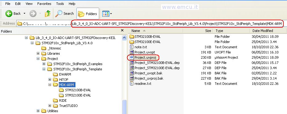
If you want receive this program (STM32-Discovery-Test) please click here.
After you have unzipped the STM32-Discovery-Test you must go in the MDK-ARM directory and double click on Project.uvproj for run the KEIL IDE, see below.
Date: April 2011
Author: Enrico Marinoni
MCU: STM32F100RBT6B
EvaBoard: STM32FVL Discovery
http://www.emcu.it/STM32Discovery/STM32ValueLineDiscovery.html
STM Library Version: V3.4.0
KEIL Version: uVision4
IDE-Version: µVision V4.10
Toolchain: RealView MDK-ARM Version: 4.12
Toolchain Path: BIN40\
C Compiler: Armcc.Exe V4.1.0.481 [Evaluation]
Assembler: Armasm.Exe V4.1.0.481 [Evaluation]
Linker/Locator: ArmLink.Exe V4.1.0.481 [Evaluation]
Librarian: ArmAr.Exe V4.1.0.481 [Evaluation]
Hex Converter: FromElf.Exe V4.1.0.481 [Evaluation]
CPU DLL: SARMCM3.DLL V4.12
Dialog DLL: DARMSTM.DLL V1.47
Target DLL: STLink\ST-LINKIII-KEIL.dll V1.5.1
Dialog DLL: TARMSTM.DLL V1.47
Software Description:
Configure SYSCLK (System clock) to 24Mhz
Send to the MCO (PA8) the SYSCLK
Configure LD3 & LD4 (Led)
LD4 flashes according with ADC measure
ADC (used on ADC1_IN10 pin PC0) in DMA mode that determines the speed of LD4 flashing
Push Button-BLUE (B1 USER) if is press the LD3 go ON
USART1 is configure to send the status of Push Button-BLUE (B1 USER - see the variable: RxChar)
The USART1 SetUp is:
USART1 used in UART1 mode
BaudRate 9600
WordLength_8b
StopBits_1
Parity_No
FlowControl_None
SPI1 (used on PA5 (CLK), PA6 (MISO), PA7 (MOSI).
SPI is configure to send the status of Push Button-BLUE (B1 USER - see the variable: SPI1val)
*
* THE PRESENT FIRMWARE WHICH IS FOR GUIDANCE ONLY AIMS AT PROVIDING CUSTOMERS
* WITH CODING INFORMATION REGARDING THEIR PRODUCTS IN ORDER FOR THEM TO SAVE
* TIME. AS A RESULT, STMICROELECTRONICS SHALL NOT BE HELD LIABLE FOR ANY
* DIRECT, INDIRECT OR CONSEQUENTIAL DAMAGES WITH RESPECT TO ANY CLAIMS ARISING
* FROM THE CONTENT OF SUCH FIRMWARE AND/OR THE USE MADE BY CUSTOMERS OF THE
* CODING INFORMATION CONTAINED HEREIN IN CONNECTION WITH THEIR PRODUCTS.
*
*/
/* Includes ------------------------------------------------------------------*/
#include "stm32f10x.h"
#include "stdio.h"
/* Private typedef -----------------------------------------------------------*/
/* Private define ------------------------------------------------------------*/
#define ADC1_DR_Address ((uint32_t)0x4001244C) // Used for ADC
/* Private macro -------------------------------------------------------------*/
/* Private variables ---------------------------------------------------------*/
GPIO_InitTypeDef GPIO_InitStructure;
RCC_ClocksTypeDef RCC_ClockFreq;
ErrorStatus HSEStartUpStatus;
ADC_InitTypeDef ADC_InitStructure; // Used for ADC
DMA_InitTypeDef DMA_InitStructure; // Used for ADC
__IO uint16_t ADCConvertedValue; // Used for ADC
USART_InitTypeDef USART_InitStructure; // Used for USART
u8 RxChar=0x0; // Used for USART
SPI_InitTypeDef SPI_InitStructure; // Used for SPI
u16 SPI1val; // Used for SPI
/* Private function prototypes -----------------------------------------------*/
void Delay(__IO uint32_t nCount);
void SetSysClockTo24(void); // Configure System Clock to HSE at 24MHz (external 8MHz crystal)
void EnableCLK(void); // Enable CLK to PORTs and Peripherals
void GPIO_Configuration(void); // Configure the I/O
void ConfigureDMAforADC(void); // Configure DMA for ADC
void NVIC_Configuration(void); // Used for USART
void ConfigureUART1(void); // Used for USART
void ConfigureSPI1(void); // Used for SPI
/* Private functions ---------------------------------------------------------*/
int main(void)
{
/* Setup the microcontroller system. Initialize the Embedded Flash Interface,
initialize the PLL and update the SystemFrequency variable. */
SystemInit();
// Sets System clock frequency to 24MHz
SetSysClockTo24();
// Enable CLK to PORTs and Peripherals
EnableCLK();
// Configure the I/O
GPIO_Configuration();
// Configure DMA for ADC
ConfigureDMAforADC();
// Configure USART1
ConfigureUART1();
// Configure SPI
ConfigureSPI1();
while (1)
{
/* Turn on LD4 - PC8 */
GPIO_SetBits ( GPIOC, GPIO_Pin_8 );
/* Insert delay */
Delay(ADCConvertedValue*100);
/* Turn off LD4 - PC8 */
GPIO_ResetBits ( GPIOC, GPIO_Pin_8 );
/* Insert delay */
Delay(ADCConvertedValue*100);
// Read BLUE Botton
if(!GPIO_ReadInputDataBit(GPIOA, GPIO_Pin_0))
{
GPIO_ResetBits ( GPIOC, GPIO_Pin_9 );
USART_SendData(USART1, '1');
SPI_I2S_SendData (SPI1, 0x1);
}
else
{
GPIO_SetBits ( GPIOC, GPIO_Pin_9 );
USART_SendData(USART1, '0');
SPI_I2S_SendData (SPI1, 0x0);
}
// Read SPI1
SPI1val=SPI_I2S_ReceiveData(SPI1);
}
}
// +++++++++ SetUp +++++++++++++++++++++++++++++++++++++++++++
void Delay(__IO uint32_t nCount)
{
for(; nCount != 0; nCount--);
}
//
// Configure SPI
//
void ConfigureSPI1(void)
{
SPI_InitStructure.SPI_Direction = SPI_Direction_2Lines_FullDuplex;
SPI_InitStructure.SPI_Mode = SPI_Mode_Master;
SPI_InitStructure.SPI_DataSize = SPI_DataSize_8b;
SPI_InitStructure.SPI_CPOL = SPI_CPOL_High;
SPI_InitStructure.SPI_CPHA = SPI_CPHA_2Edge;
SPI_InitStructure.SPI_NSS = SPI_NSS_Soft;
SPI_InitStructure.SPI_BaudRatePrescaler = SPI_BaudRatePrescaler_64;
SPI_InitStructure.SPI_FirstBit = SPI_FirstBit_MSB;
SPI_InitStructure.SPI_CRCPolynomial = 7;
SPI_Init(SPI1, &SPI_InitStructure);
SPI_Cmd(SPI1, ENABLE); /* Enable the SPI */
}
//
// Configure UART1
//
void ConfigureUART1(void)
{
/* USART1 configured as follow:
- BaudRate = 9600 baud
- Word Length = 8 Bits
- ONE Stop Bit
- NO parity
- Hardware flow control disabled (RTS and CTS signals)
- Receive and transmit enabled
*/
USART_InitStructure.USART_BaudRate = 9600;
USART_InitStructure.USART_WordLength = USART_WordLength_8b;
USART_InitStructure.USART_StopBits = USART_StopBits_1;
USART_InitStructure.USART_Parity = USART_Parity_No;
USART_InitStructure.USART_HardwareFlowControl = USART_HardwareFlowControl_None;
USART_InitStructure.USART_Mode = USART_Mode_Rx | USART_Mode_Tx;
USART_Init(USART1, &USART_InitStructure); // Configure the USART1
/* Enable the USART Transmit interrupt: this interrupt is generated when the
USART1 transmit data register is empty */
USART_ITConfig(USART1, USART_IT_TXE, ENABLE);
/* Enable the USART Receive interrupt: this interrupt is generated when the
USART1 receive data register is not empty */
USART_ITConfig(USART1, USART_IT_RXNE, ENABLE);
/* Enable USART1 */
USART_Cmd(USART1, ENABLE);
}
//
// Configure DMA for ADC
//
void ConfigureDMAforADC(void)
{
/* DMA1 channel1 configuration ----------------------------------------------*/
DMA_DeInit(DMA1_Channel1);
DMA_InitStructure.DMA_PeripheralBaseAddr = ADC1_DR_Address;
DMA_InitStructure.DMA_MemoryBaseAddr = (uint32_t)&ADCConvertedValue;
DMA_InitStructure.DMA_DIR = DMA_DIR_PeripheralSRC;
DMA_InitStructure.DMA_BufferSize = 1;
DMA_InitStructure.DMA_PeripheralInc = DMA_PeripheralInc_Disable;
DMA_InitStructure.DMA_MemoryInc = DMA_MemoryInc_Disable;
DMA_InitStructure.DMA_PeripheralDataSize = DMA_PeripheralDataSize_HalfWord;
DMA_InitStructure.DMA_MemoryDataSize = DMA_MemoryDataSize_HalfWord;
DMA_InitStructure.DMA_Mode = DMA_Mode_Circular;
DMA_InitStructure.DMA_Priority = DMA_Priority_High;
DMA_InitStructure.DMA_M2M = DMA_M2M_Disable;
DMA_Init(DMA1_Channel1, &DMA_InitStructure);
/* Enable DMA1 channel1 */
DMA_Cmd(DMA1_Channel1, ENABLE);
/* ADC1 configuration ------------------------------------------------------*/
ADC_InitStructure.ADC_Mode = ADC_Mode_Independent;
ADC_InitStructure.ADC_ScanConvMode = ENABLE;
ADC_InitStructure.ADC_ContinuousConvMode = ENABLE;
ADC_InitStructure.ADC_ExternalTrigConv = ADC_ExternalTrigConv_None;
ADC_InitStructure.ADC_DataAlign = ADC_DataAlign_Right;
ADC_InitStructure.ADC_NbrOfChannel = 1;
ADC_Init(ADC1, &ADC_InitStructure);
/* ADC1 regular channel 10 configuration */
ADC_RegularChannelConfig(ADC1, ADC_Channel_10, 1, ADC_SampleTime_55Cycles5);
/* Enable ADC1 DMA */
ADC_DMACmd(ADC1, ENABLE);
/* Enable ADC1 */
ADC_Cmd(ADC1, ENABLE);
/* Enable ADC1 reset calibaration register */
ADC_ResetCalibration(ADC1);
/* Check the end of ADC1 reset calibration register */
while(ADC_GetResetCalibrationStatus(ADC1));
/* Start ADC1 calibaration */
ADC_StartCalibration(ADC1);
/* Check the end of ADC1 calibration */
while(ADC_GetCalibrationStatus(ADC1));
/* Start ADC1 Software Conversion */
ADC_SoftwareStartConvCmd(ADC1, ENABLE);
}
//
// Configure the I/O
//
void GPIO_Configuration(void)
{
/* Configure Leds (PC8 & PC9) mounted on STM32 Discovery board - OutPut Push Pull*/
GPIO_InitStructure.GPIO_Pin = GPIO_Pin_8 | GPIO_Pin_9;
GPIO_InitStructure.GPIO_Mode = GPIO_Mode_Out_PP;
GPIO_InitStructure.GPIO_Speed = GPIO_Speed_50MHz;
GPIO_Init(GPIOC, &GPIO_InitStructure);
// Configure BLUE Botton (B1 User - PA0) on STM32 Discovery board - Input Floatting
GPIO_InitStructure.GPIO_Pin = GPIO_Pin_0;
GPIO_InitStructure.GPIO_Mode = GPIO_Mode_IN_FLOATING;
GPIO_Init(GPIOA, &GPIO_InitStructure);
// Configure ADC on ADC1_IN10 pin PC0
GPIO_InitStructure.GPIO_Pin = GPIO_Pin_0;
GPIO_InitStructure.GPIO_Mode = GPIO_Mode_AIN;
GPIO_Init(GPIOC, &GPIO_InitStructure);
/* Configure USART1 Tx (PA9) as alternate function push-pull */
GPIO_InitStructure.GPIO_Pin = GPIO_Pin_9;
GPIO_InitStructure.GPIO_Speed = GPIO_Speed_2MHz;
GPIO_InitStructure.GPIO_Mode = GPIO_Mode_AF_PP;
GPIO_Init(GPIOA, &GPIO_InitStructure);
/* Configure USART1 Rx (PA10) as input floating */
GPIO_InitStructure.GPIO_Pin = GPIO_Pin_10;
GPIO_InitStructure.GPIO_Mode = GPIO_Mode_IN_FLOATING;
GPIO_Init(GPIOA, &GPIO_InitStructure);
// Configure SPI - CLK PA5, MISO PA6, MOSI PA7
GPIO_InitStructure.GPIO_Pin = GPIO_Pin_5 | GPIO_Pin_6 | GPIO_Pin_7;
GPIO_InitStructure.GPIO_Speed = GPIO_Speed_2MHz;
GPIO_InitStructure.GPIO_Mode = GPIO_Mode_AF_PP;
GPIO_Init(GPIOA, &GPIO_InitStructure);
}
/**
* Sets System clock frequency to 24MHz and configure HCLK, PCLK2
* and PCLK1 prescalers.
* param None
* retval None
*/
void SetSysClockTo24(void)
{
/* SYSCLK, HCLK, PCLK2 and PCLK1 configuration -----------------------*/
/* RCC system reset(for debug purpose) */
RCC_DeInit();
/* Enable HSE */
RCC_HSEConfig(RCC_HSE_ON);
/* Wait till HSE is ready */
HSEStartUpStatus = RCC_WaitForHSEStartUp();
if (HSEStartUpStatus == SUCCESS)
{
/* Flash 0 wait state */
FLASH_SetLatency(FLASH_Latency_0);
/* HCLK = SYSCLK */
RCC_HCLKConfig(RCC_SYSCLK_Div1);
/* PCLK2 = HCLK */
RCC_PCLK2Config(RCC_HCLK_Div1);
/* PCLK1 = HCLK */
RCC_PCLK1Config(RCC_HCLK_Div1);
/* PLLCLK = (8MHz/2) * 6 = 24 MHz */
RCC_PREDIV1Config(RCC_PREDIV1_Source_HSE, RCC_PREDIV1_Div2);
RCC_PLLConfig(RCC_PLLSource_PREDIV1, RCC_PLLMul_6);
/* Enable PLL */
RCC_PLLCmd(ENABLE);
/* Wait till PLL is ready */
while (RCC_GetFlagStatus(RCC_FLAG_PLLRDY) == RESET)
{
}
/* Select PLL as system clock source */
RCC_SYSCLKConfig(RCC_SYSCLKSource_PLLCLK);
/* Wait till PLL is used as system clock source */
while (RCC_GetSYSCLKSource() != 0x08)
{
}
}
else
{
/* If HSE fails to start-up, the application will have wrong clock configuration.
User can add here some code to deal with this error */
/* Go to infinite loop */
while (1)
{
}
}
}
//
// Enable CLK to PORTs and Peripherals
//
void EnableCLK(void)
{
// Enable CLK to port ADC1, GPIOC/A, USART1, SPI1
RCC_APB2PeriphClockCmd(RCC_APB2Periph_ADC1 | RCC_APB2Periph_GPIOC | RCC_APB2Periph_GPIOA | RCC_APB2Periph_USART1
| RCC_APB2Periph_SPI1, ENABLE);
/* Enable DMA1 clock */
RCC_AHBPeriphClockCmd(RCC_AHBPeriph_DMA1, ENABLE);
/* Fills the RCC_ClockFreq structure with the current
frequencies of different on chip clocks (for debug purpose) */
RCC_GetClocksFreq(&RCC_ClockFreq);
}
#ifdef USE_FULL_ASSERT
void assert_failed(uint8_t* file, uint32_t line)
{
/* User can add his own implementation to report the file name and line number,
ex: printf("Wrong parameters value: file %s on line %d\r\n", file, line) */
/* Infinite loop */
while (1)
{
}
}
#endif
/***********************END OF FILE****/
If you want receive this program (STM32-Discovery-Test) please click here.
After you have unzipped the STM32-Discovery-Test you must go in the MDK-ARM directory and double click on Project.uvproj for run the KEIL IDE, see below.
stm32f10x_conf.h
Peripheral’s drivers configuration file.
The user can enable or disable peripheral header file inclusion.
This file can also be used to enable or disable the Library run-time failure detection before compiling the firmware library drivers, through the preprocessor define USE_FULL_ASSERT
/* Includes ------------------------------------------------------------------*/
/* Uncomment the line below to enable peripheral header file inclusion */
/* #include "stm32f10x_adc.h" */
/* #include "stm32f10x_bkp.h" */
/* #include "stm32f10x_can.h" */
/* #include "stm32f10x_cec.h" */
/* #include "stm32f10x_crc.h" */
/* #include "stm32f10x_dac.h" */
/* #include "stm32f10x_dbgmcu.h" */
/* #include "stm32f10x_dma.h" */
#include "stm32f10x_exti.h"
/* #include "stm32f10x_flash.h" */
/* #include "stm32f10x_fsmc.h" */
#include "stm32f10x_gpio.h"
/* #include "stm32f10x_i2c.h" */
/* #include "stm32f10x_iwdg.h" */
/* #include "stm32f10x_pwr.h" */
#include "stm32f10x_rcc.h"
/* #include "stm32f10x_rtc.h" */
/* #include "stm32f10x_sdio.h" */
#include "stm32f10x_spi.h"
/* #include "stm32f10x_tim.h" */
#include "stm32f10x_usart.h"
/* #include "stm32f10x_wwdg.h" */
#include "misc.h" /* High level functions for NVIC and SysTick (add-on to CMSIS functions) */
stm32f10x.h
User has to include it (under Libraries\CMSIS\CM3\DeviceSupport\ST\STM32F10x) in the application main and configure for select the target product family to be used, comment/uncomment the right define:
/* Uncomment the line below according to the target STM32 device used in your
application
*/
#if !defined (STM32F10X_LD) && !defined (STM32F10X_LD_VL) && !defined (STM32F10X_MD) && !defined (STM32F10X_MD_VL) && !defined (STM32F10X_HD) && !defined (STM32F10X_XL) && !defined (STM32F10X_CL)
/* #define STM32F10X_LD */ /*!< STM32F10X_LD: STM32 Low density devices */
#define STM32F10X_LD_VL /*!< STM32F10X_LD_VL: STM32 Low density Value Line devices */
/* #define STM32F10X_MD */ /*!< STM32F10X_MD: STM32 Medium density devices */
/* #define STM32F10X_MD_VL */ /*!< STM32F10X_MD_VL: STM32 Medium density Value Line devices */
/* #define STM32F10X_HD */ /*!< STM32F10X_HD: STM32 High density devices */
// #define STM32F10X_XL /*!< STM32F10X_XL: STM32 XL-density devices */
/* #define STM32F10X_CL */ /*!< STM32F10X_CL: STM32 Connectivity line devices */
#endif
/* Tip:
To avoid modifying this file each time you need to switch between these devices, you can define the device in your toolchain compiler preprocessor.
- Low density devices are STM32F101xx, STM32F102xx and STM32F103xx microcontrollers
where the Flash memory density ranges between 16 and 32 Kbytes.
- Low-density value line devices are STM32F100xx microcontrollers where the Flash
memory density ranges between 16 and 32 Kbytes.
- Medium density devices are STM32F101xx, STM32F102xx and STM32F103xx microcontrollers
where the Flash memory density ranges between 64 and 128 Kbytes.
- Medium-density value line devices are STM32F100xx microcontrollers where the
Flash memory density ranges between 64 and 128 Kbytes.
- High density devices are STM32F101xx and STM32F103xx microcontrollers where
the Flash memory density ranges between 256 and 512 Kbytes.
- XL-density devices are STM32F101xx and STM32F103xx microcontrollers where
the Flash memory density ranges between 512 and 1024 Kbytes.
- Connectivity line devices are STM32F105xx and STM32F107xx microcontrollers.
*/
system_stm32f10x.c
Add the system_stm32f10x.c (under Libraries\CMSIS\CM3\DeviceSupport\ST\STM32F10x) file in your application, this file provide functions to
setup the STM32 system:
configure the PLL, system clock and initialize the Embedded Flash Interface.
This file provides multiple choice for the system clock max frequency, you can selected the frequency needed for your application from the list below (common frequencies that covers the major of the applications):
/*!< Uncomment the line corresponding to the desired System clock (SYSCLK)
frequency (after reset the HSI is used as SYSCLK source)
IMPORTANT NOTE:
==============
1. After each device reset the HSI is used as System clock source.
2. Please make sure that the selected System clock doesn't exceed your device's
maximum frequency.
3. If none of the define below is enabled, the HSI is used as System clock
source.
4. The System clock configuration functions provided within this file assume that:
- For Low and Medium density Value line devices an external 8MHz crystal
is used to drive the System clock.
- For Low, Medium and High density devices an external 8MHz crystal is
used to drive the System clock.
- For Connectivity line devices an external 25MHz crystal is used to drive
the System clock.
If you are using different crystal you have to adapt those functions accordingly.
*/
#if defined (STM32F10X_LD_VL) || (defined STM32F10X_MD_VL)
/* #define SYSCLK_FREQ_HSE HSE_Value */
#define SYSCLK_FREQ_24MHz 24000000
#else
/* #define SYSCLK_FREQ_HSE HSE_Value */
#define SYSCLK_FREQ_24MHz 24000000
/* #define SYSCLK_FREQ_36MHz 36000000 */
/* #define SYSCLK_FREQ_48MHz 48000000 */
/* #define SYSCLK_FREQ_56MHz 56000000 */
// #define SYSCLK_FREQ_72MHz 72000000
#endif
Note:
The System clock configuration functions provided within this file assume that:
- For Low-density Value line, Low-density, Medium-density Value line, Medium-density and High-density devices an external 8MHz is used to drive the System clock.
- For Connectivity line devices an external 25MHz crystal is used to drive the System clock.
If you are using different crystal you have to change the value of the define HSE_VALUE in stm32f10x.h file and adapt those functions accordingly.
stm32f10x_it.h
Header file including all interrupt handlers prototypes.
stm32f10x_it.c
Template source file containing the interrupt service routine (ISR) for CortexM3 exceptions. User can add additional ISR(s) for the used peripheral(s) (for the available peripheral interrupt handler's name, please refer to the startup file startup_stm32f10x_xx.s).