STM32F0xx Page
SetUp
Basic Functions
Suggested improvement
Electronic scheme
Software & Doc
-
Introduction
ATTENTION:
This FW is an alpha release this means that is not fully tested. Remember also that:
This project is a real application of the concepts discussed here.
By this FW you are ready to drive an automatic Single Swing Gate.
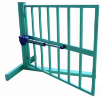
This project is based on the STM32F0-Discovery.
As it is a custom project, are present the uncommon functions listed below:
- Crepuscular light sensor that turns on the outside lights at night. When the gate is closed the lights is turn off after a time that depend of the value of the Temp.RLuci (RegularConvData_Tab[0]).
- Blinking LAMP at 220Vac (it indicates that the gate is in motion).
- Input for PHOTOCELL but if for your application is a mandatory, you simply connect an external Photocell to PE input that stop the gate.
- Input for Remote Control but if for your application is a mandatory, you simply connect an external Remote Control to PP input.
-
SetUp
The LEDs and PulsBLU are on STM32F0-Discovery.
| Led BLU | Led GREEN | Explanation | Note |
OFF |
Flashing |
Normal working |
|
Flashing |
OFF |
Indicate the request of the: programming open time for single swing gate. |
To program this time see: PulsBLU |
Flashing |
Flashing |
Indefinite situation - the gate not knows what to do |
Check the operation of the: FCA and FCC that for swing gate must be opened. If you are using a Swing Gate reprogram the time of opening, see PulsBLU. |
PulsBLU |
SetUp Used to configure the opening time. |
Afther the PowerON if PulsBLU is pressed, it is started the routine that allows you to set the run time for the swing gate (SetUp). After you are started the SetUp, release the PulsBLU and then follow the steps below (see steps: 1 and 2). During the first installation, if the gate is configured as a swing gate, automaticaly you are in the routine that allows you to set the run time for the swing gate. For configure the run time, follow the steps below. 1) Place the gate CLOSED 2) Press the BLUE button to fully open up the gate and then release it. At this point the gate is programmed and will automatically close. |
Basic Functions
StatoLampeggioLedVerde
= SPENTO;
The
blinking Green LED is OFF
StatoLampeggioLedVerde
= ACCESO;
The
blinking Green LED is ON
VLed_OFF;
The
Green LED is turned OFF
StatoLampeggioLedBlu
= SPENTO;
The
blinking Blue LED is OFF
StatoLampeggioLedBlu
= ACCESO;
The
blinking Blue LED is ON
BLed_OFF;
The
Blue LED is turned OFF
statoLampeggiante
= SPENTO;
The
blinking LAMP is OFF
statoLampeggiante
= ACCESO;
The
blinking LAMP is ON
LAMP_OFF;
The
LAMP is turned OFF
AttesaPressioneTastoBLU();
Waiting
until the Blue Button is pressed and released.
The
Blue Button is on the STM32F0-Discovery.
Delay(n);
Set
a delay of n ms. If n==1000 the delay is 1sec
The ADC input channels are used under DMA and the allocation is show below.
|
Name |
Simbol |
PIN |
Function |
Name of channel |
Tab position |
|
Tempo Luce di Cortesia |
TLC |
PA1 |
Analog |
ADC_Channel_1 |
RegularConvData_Tab[0] |
|
Crepuscolare |
CRE |
PA7 |
Analog |
ADC_Channel_7 |
RegularConvData_Tab[1] |
|
Reserved |
PWM |
PA3 |
Analog |
ADC_Channel_3 |
RegularConvData_Tab[2] |
|
Sensibilità Crepuscolare |
SC |
PA2 |
Analog |
ADC_Channel_2 |
RegularConvData_Tab[3] |
Tempo Luce di Cortesia ---> Time Courtesy Light
Crepuscolare ---> CrepuscularSensibilità crepuscolare ---> Tensitivity Crepuscular
Suggested improvement
Add a motor speed control also called: gate’s final opening/closing phase slow-down speeds.
-
Electronic scheme
The electronic scheme is below, for see large image click on it.
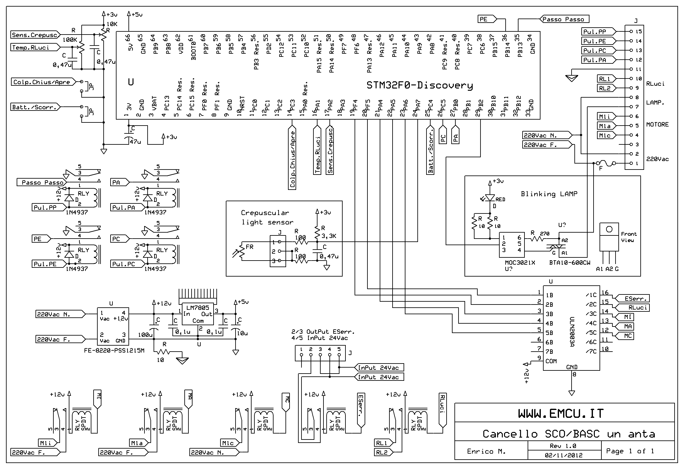
Remember to dissipate the LM7805.
The FR (PHOTORESISTOR) is 2..20K, 100mW and it is find here (cod.2510-LDR04) and here (LDR04).
The FE-8220-PSS1215M also called PSS1215M and it is find here (cod.8220-PSS1215M) and here.
Below there are some photo of my board.
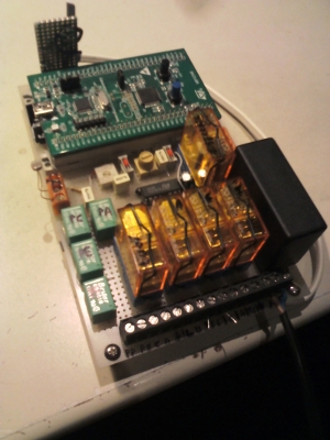
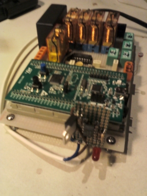
-
Software and Doc
For download the Software and Doc click here and download: STM32F0-AutomaticGateRA
This SW was tested on KEIL ver.5.10.0.2 - 32K free version.
that is in the folder:
C:\......\F0_CANCbatsco_LibV1.0.0\Project\STM32F0xx_StdPeriph_Templates\MDK-ARM
Inside the directory tree there are the folders below.
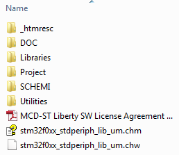
In the DOC folder there are the components data sheet and .bmp and .xls file.
Also there are some .bmp files with other explanations.
In the SCHEMI folder there is the electronic scheme.