
Home
Page
STM32F4xx Page
STM32F4xx Page
ATTENTION:
For using this example is necessary remove the TFT from the STM32F429I-DISCO, see below.

This example shows the mode to use of the:
LEDs
LD3 Green PG13
LD4 Red PG14
Blue Button
BlueButton PA0 WKUP
SPI1
SPI1_MISO PA6
SPI1_MOSI PA7
SPI1_SCK PA5
CAN1
CAN1_RX PD0
CAN1_TX PD1
Firmware, IDE & Optimizations:
Firmware Package Name and Version: STM32Cube FW_F4 V1.5.0
Toolchain/IDE: MDK-ARM V5
Compiler Optimizations: Balanced Size/Speed
How to use this example:
1) After the RESET both LEDs are blinking fast.
2) Press the BLUE BUTTON for start the CAN1 loopback test.
If the CAN1 test is OK, the Green Led is on for 2sec
If the CAN1 test is FAIL, the Red Led is on for 2sec
3) After the CAN1 test, both LEDs are blinking fast.
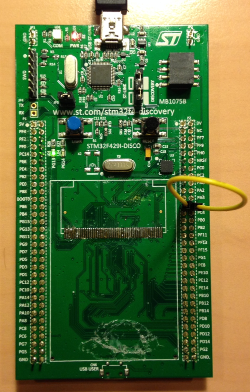
4) Press the BLUE BUTTON for start the SPI1 polling test , connect PA6 to PA7 (see below).
If the SPI1 test is OK, the Green Led is on for 2sec
If the SPI1 test is FAIL, the Red Led is on for 2sec
5) After the SPI1 polling test, both LEDs are blinking slowly.
If you press the BLUE BOTTON both LEDs are on for 2sec
The SW return to point n.5
The SW Cod.Ref. is: Co3bApr2015 and is here.
The SW is free example.
For using this example is necessary remove the TFT from the STM32F429I-DISCO, see below.
This example shows the mode to use of the:
LEDs
LD3 Green PG13
LD4 Red PG14
Blue Button
BlueButton PA0 WKUP
SPI1
SPI1_MISO PA6
SPI1_MOSI PA7
SPI1_SCK PA5
CAN1
CAN1_RX PD0
CAN1_TX PD1
Firmware, IDE & Optimizations:
Firmware Package Name and Version: STM32Cube FW_F4 V1.5.0
Toolchain/IDE: MDK-ARM V5
Compiler Optimizations: Balanced Size/Speed
How to use this example:
1) After the RESET both LEDs are blinking fast.
2) Press the BLUE BUTTON for start the CAN1 loopback test.
If the CAN1 test is OK, the Green Led is on for 2sec
If the CAN1 test is FAIL, the Red Led is on for 2sec
3) After the CAN1 test, both LEDs are blinking fast.
4) Press the BLUE BUTTON for start the SPI1 polling test , connect PA6 to PA7 (see below).
If the SPI1 test is OK, the Green Led is on for 2sec
If the SPI1 test is FAIL, the Red Led is on for 2sec
5) After the SPI1 polling test, both LEDs are blinking slowly.
If you press the BLUE BOTTON both LEDs are on for 2sec
The SW return to point n.5
The SW Cod.Ref. is: Co3bApr2015 and is here.
The SW is free example.