How to implement an
Input reading with debounce
and test it on STM8S Discovery
Suggested
reading:
Preconditions:
Click here to get this SW Example ready to use, inside there is the excel sheet (STM8-Discovery-TIM4-Input_with_Debounce)
First, please reading the:
How to configure TIM4 to 1mS and test it on STM8S Discovery, (click here).
The mechanical properties of a switch, when a switch is pressed, there is a period of time in which the electrical connection "bounces" between open and closed.
It is important chose good Debounce Time for filtering the digital input noise.
Normaly the Deboundance Time must be from 5 to 30mS.
There are typically 2 methods employed to debounce a swtich:
What we want to do is reading and Input and implement a method for the debounce.
The idea is to use the TIM4 configured to generate an interrupt every 1mS and use this interrupt for implementing the Input debounce.
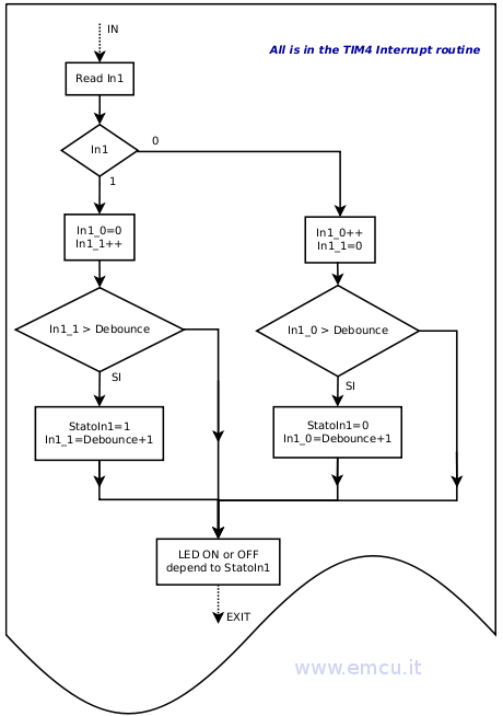
The flow diagram is below.
Note that using the flow below the Input is recognize at 1 or 0 if it stay at 1 or 0 for a time > of Debounce.
In another words, the 1 or the 0 must be 1 or 0 for all the Debounce Time.
If during the samples the imput change from 0 to 1 to 0 ecc, every change reset the In1_0 and In1_1. In this way when In1_0 or In1_1 exceeds Debounce means that it were at 1 or 0 for at least of the Debounce Time.
First we declared a global variables that are showed below.
The variable named: Debounce indicates the time that must pass to accept valid input.
Debounce is a multiple of 1mS.
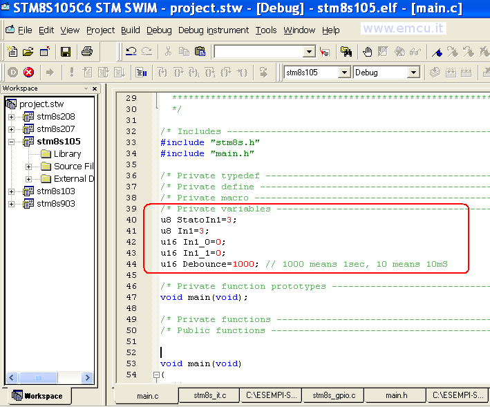
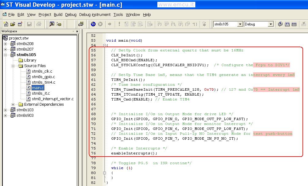
The second step is the MCU configuration, see below, line 55...76
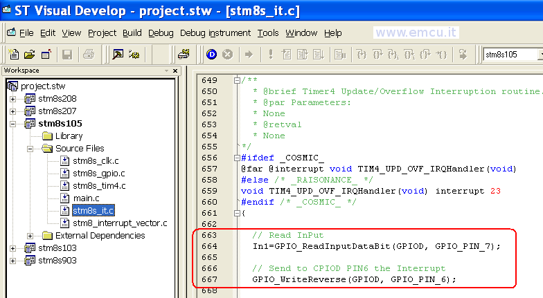
Inside the Interrupt of TIM4 there is the reading of GPIOD PIN_7 and the reverse output to flash GPIOD PIN_6.
PIN_6 is used for monitoring the Interrupt of TIM4.
See below, lines 663...667
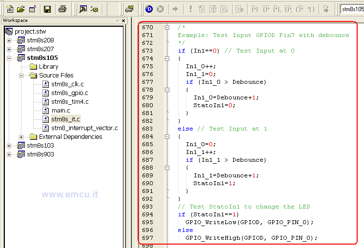
In the box below, lines 670...697, there is the implementation of the flow diagram above.
For the software this is all.
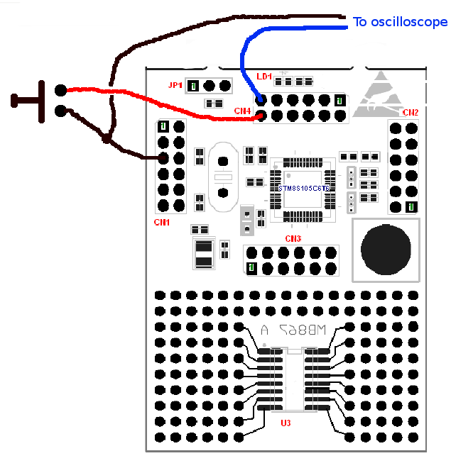
Now, for testing this SW on STM8S Discovery, the connections are show below.
- How to configure TIM4 to
1mS and test it on STM8S Discovery, click here
- UM0817: STM8S Discovery user manual is here.
- STM8S105xx DATASHEET is here.
- RM0016: REFERENCE MANUALS is here.
- PM0051: How to program STM8S Flash
program memory and data EEPROM is here.
- Flow diagram for developing software in C on STM8 - click here
Preconditions:
- The PC operating system is Windows XP SP3.
- In the PC are installed
the:
- The example below is based on STM8S Discovery.
- What does the example:
The example explains how to configure:
TIM4 to 1mS
Implement a routine to read an Input with debounce
and test it on STM8S Discovery.
Click here to get this SW Example ready to use, inside there is the excel sheet (STM8-Discovery-TIM4-Input_with_Debounce)
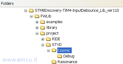
The
project was tested with Cosmic C
Compiler, the tree of the project is:
First, please reading the:
How to configure TIM4 to 1mS and test it on STM8S Discovery, (click here).
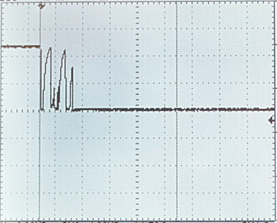
The mechanical properties of a switch, when a switch is pressed, there is a period of time in which the electrical connection "bounces" between open and closed.
It is important chose good Debounce Time for filtering the digital input noise.
Normaly the Deboundance Time must be from 5 to 30mS.
"Bouncing" of a switch shown on an oscilloscope
There are typically 2 methods employed to debounce a swtich:
using
timer and interrupt to test the state of the switch
using polling method to test the state of the switch
In
this tutorial, we will be debouncing the swith using the timer and interrupt.
using polling method to test the state of the switch
What we want to do is reading and Input and implement a method for the debounce.
The idea is to use the TIM4 configured to generate an interrupt every 1mS and use this interrupt for implementing the Input debounce.
The flow diagram is below.
Note that using the flow below the Input is recognize at 1 or 0 if it stay at 1 or 0 for a time > of Debounce.
In another words, the 1 or the 0 must be 1 or 0 for all the Debounce Time.
If during the samples the imput change from 0 to 1 to 0 ecc, every change reset the In1_0 and In1_1. In this way when In1_0 or In1_1 exceeds Debounce means that it were at 1 or 0 for at least of the Debounce Time.
First we declared a global variables that are showed below.
The variable named: Debounce indicates the time that must pass to accept valid input.
Debounce is a multiple of 1mS.
The second step is the MCU configuration, see below, line 55...76
Inside the Interrupt of TIM4 there is the reading of GPIOD PIN_7 and the reverse output to flash GPIOD PIN_6.
PIN_6 is used for monitoring the Interrupt of TIM4.
See below, lines 663...667
In the box below, lines 670...697, there is the implementation of the flow diagram above.
For the software this is all.
Now, for testing this SW on STM8S Discovery, the connections are show below.
LINK: