Home
Page
STM32 Page
INDEX
Introduction
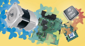
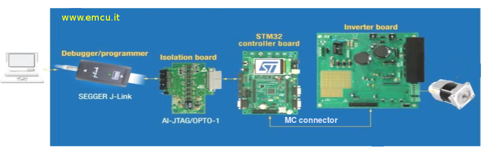
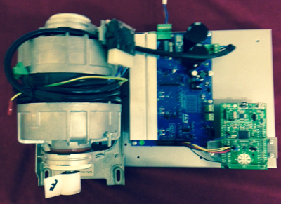
A generic motor controller kit is show below.
ST’s STM32 offers the performance of the industry-standard Cortex®-M core at the service of vector (or field-oriented) control (FOC) algorithms, widely used in high-performance drives.
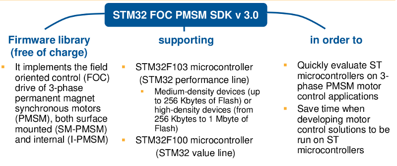
The STM32 PMSM FOC SDK(STSW-STM32100), which includes the PMSM FOC FW library and ST MC Workbench, allows the user to evaluate the STM32 performance in applications driving single or dual Field Oriented Control of 3-phase Permanent Magnet motors (PMSM, BLDC).
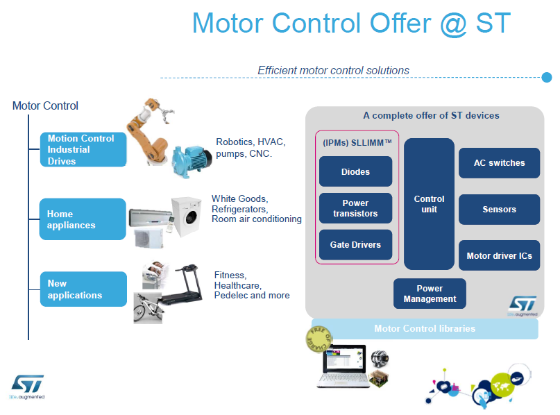
STM32 PMSM FOC SDK is part of ST's motor control ecosystem which offers a wide range of hardware and software solutions for motor control applications.
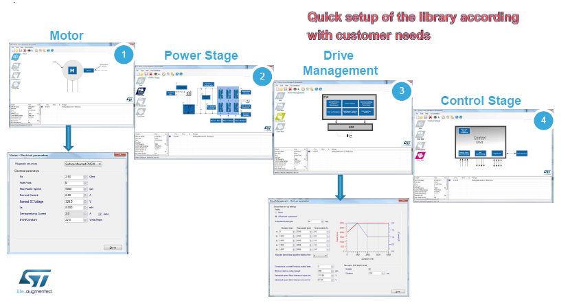
ST MC Workbench is a PC software which reduces the design effort and time in the STM32 PMSM FOC firmware library configuration.
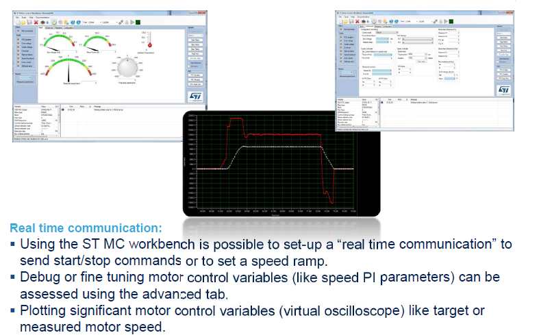
The user, through a graphical user interface (GUI), generates all parameter header files which configure the library according to the application needs and can in real time monitor and change some variables of the algorithm.
Presentation of the FOC controller
Summary MCUs and Features


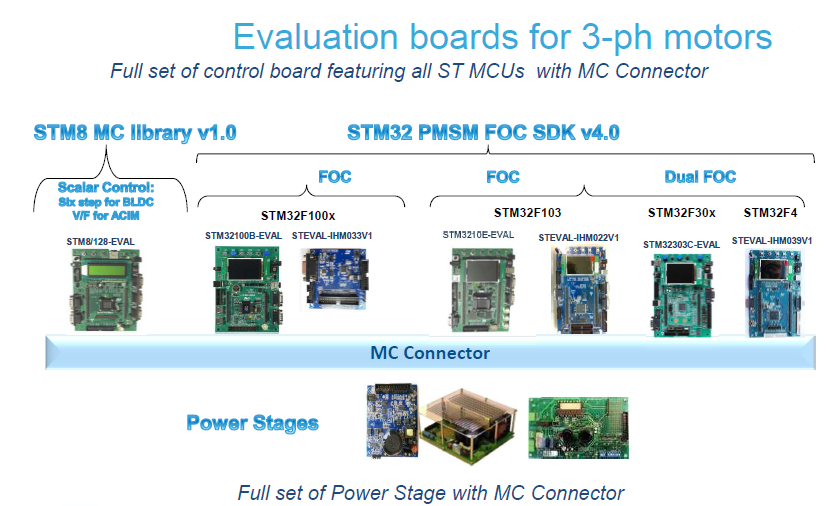
EvaBoard
 Click here to get presentation concerning STEVAL-IHM036V1
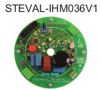
The purpose of the STEVAL-IHM036V1 demonstration board is to present a universal, fully-tested design consisting of a 3-phase inverter bridge based on the 600 V, 3 A small low-loss intelligent molded module (SLLIMM™) STGIPN3H60 and the STM32F100C6T6B MCU.
Click here for: STEVAL-IHM036V1 website.
Click here for: Quick reference guide for testing STEVAL-IHM036V1 with SHIMANO motor.
-
How to convert RPM to the Frequency of the sinusoidal current that must be generated for each phase, considering the number of pole pairs.
FOC 4.0 only for SILICA internal use
Only for SILICA internal use there is the: STM32_FOC_SDK_4.0.0_Confidential_140630
IMPORTANT NOTE
-
Training FOC 4.0 and Analog - Catania Luglio 2014 - Only for SILICA internal use
Only for SILICA internal use there is the: Training Motor control Catania 2014
IMPORTANT NOTE
-
Motor Control v.2.0 - ACIM and PMSM - only for SILICA internal use
Only for SILICA internal use there is the: Motor Control v.2.1.200(Beta) - ACIM and PMSM
IMPORTANT NOTE
LINK
STM32 Page
INDEX
- Introduction
- Presentation of the FOC controller
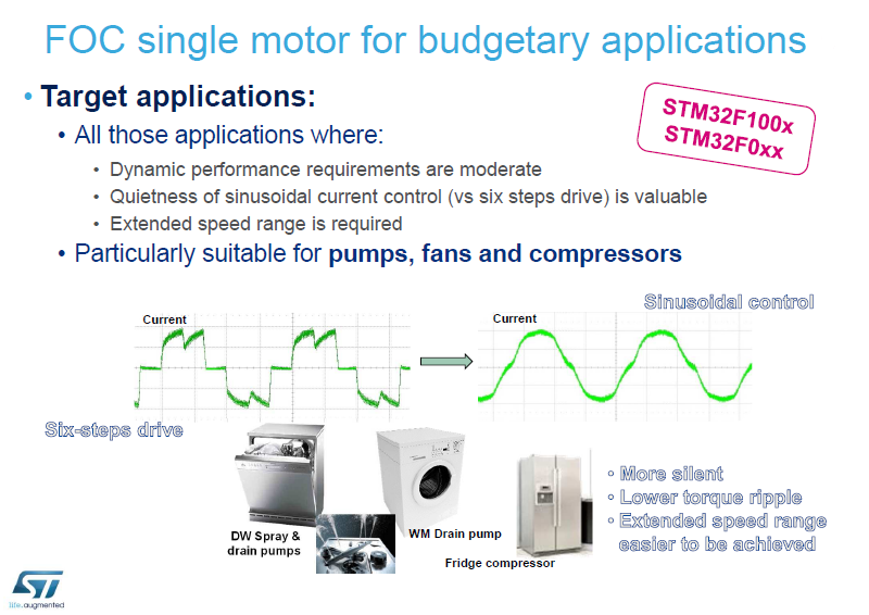
- FOC single motor for budgetary applications
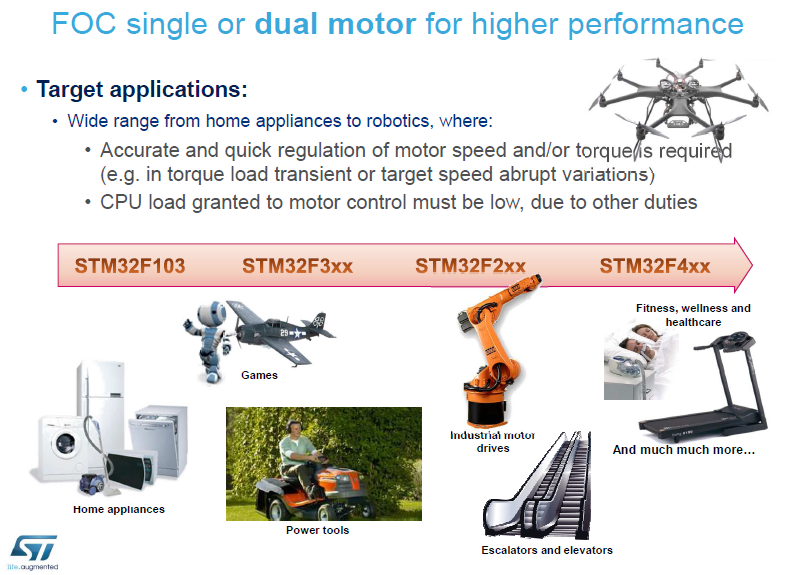
- FOC single or dual motor for higher performance
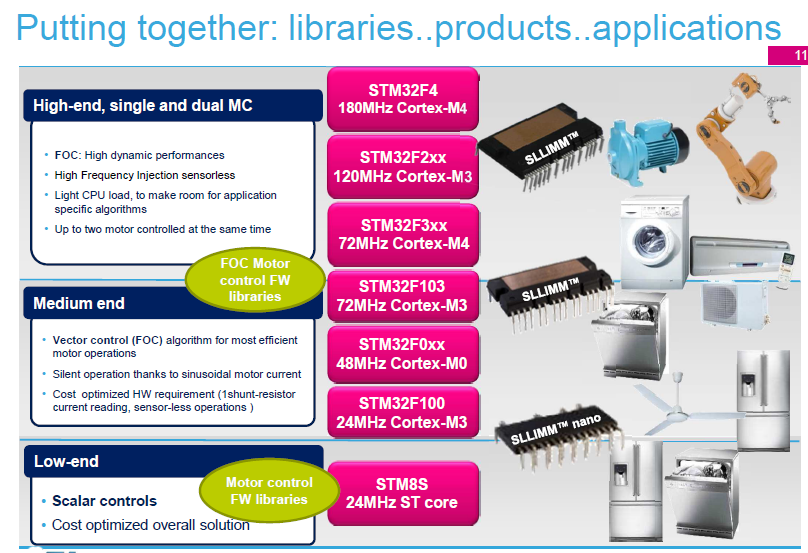
- Putting together: libraries..products..applications
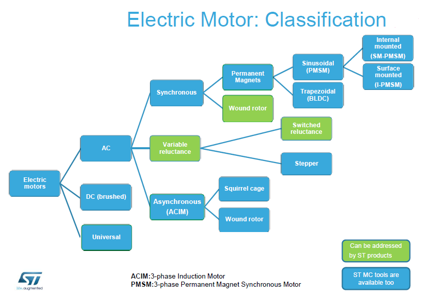
- Motor Classification
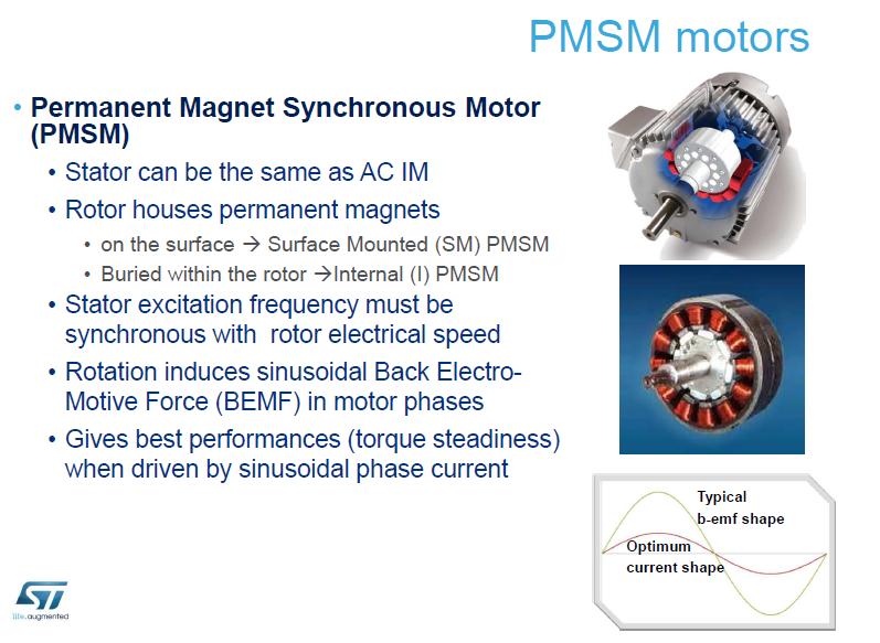
- PMSM motors
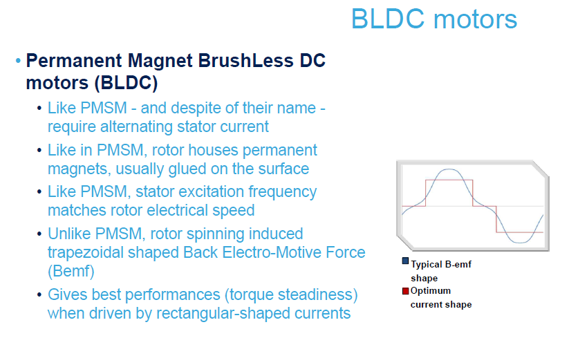
- BLDC motors
- Benefits of FOC
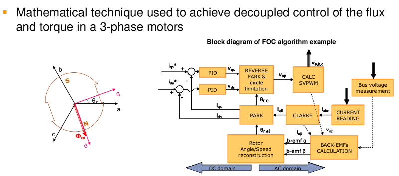
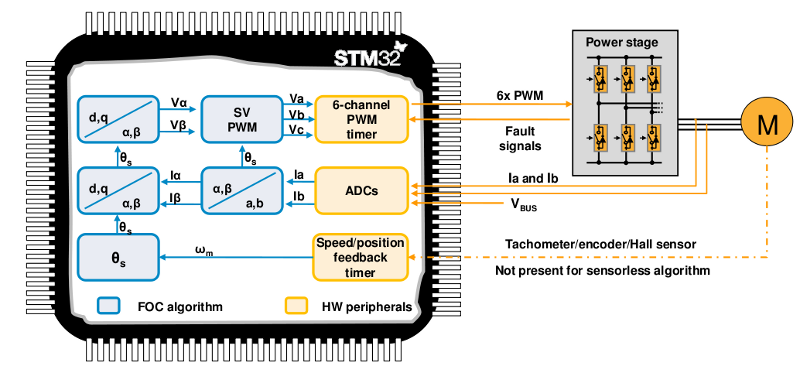
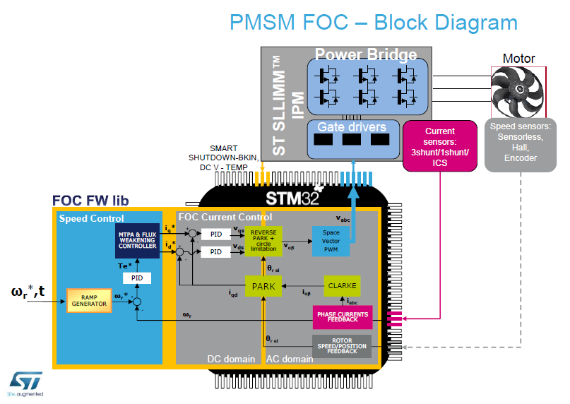
- PMSM FOC – Block Diagram
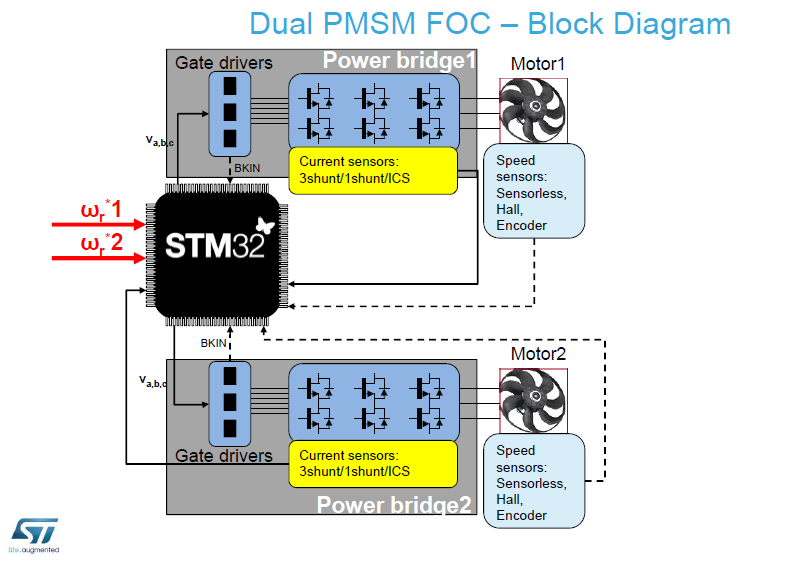
- Dual PMSM FOC – Block Diagram
- STM32 PMSM FOC SDK v.4.0
- Mathematical technique used to achive decoupled control flux an torque in 3-phase motors
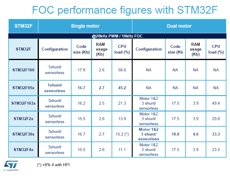
- FOC performance
- Summary MCUs and Features
- 13 workspaces available
- Eva Boards
- NUCLEO FOC KIT
- Motor Contro v.4 - Technical and MKT presentation
- List of: Motor Control Solution Eval Boards
- How to update the GUI on PC and on STM32 Eval Boards for using the FOC Motor Control Kit (Motor Control Workbench)
- How to convert RPM to the Frequency of the sinusoidal current that must be generated for each phase, considering the number of pole pairs.
-
ST solutions for efficient motor control
• Electric motors classification
• Nomenclature
• Scalar and vector drives
• ST motor control ‘Ecosystem’
• Focus on vector control
• Nomenclature
• Scalar and vector drives
• ST motor control ‘Ecosystem’
• Focus on vector control
- RESERVED files
The below DOC and FW are only for SILICA and STM customers.
If you is SILICA customer, please ask me the password.
Please specify your Name, CITY, COUNTRY and your contact in SILICAIf you are STM customers, please contact STM office.
- STM32 - How to use FOC ver.4.2
- STM32_3phase_FOC_PSM_MC_library_Tutorial_v4.1.0 (Italian version)
- STM32_3phase PMSM MC library in deep explanation (MC_Library400_Training)
- STM32_3phase_FOC_PSM_MC_library_Tutorial_v4.0.0
- Training FOC 4.0 and Analog - Catania Luglio 2014
- Motor Control v.2.1.200(Beta) - ACIM and PMSM
- V/F motor control
- V/F ver.alfa1 for STM33F3xx - see here the V/F in action
- V/F ver.1.1.0 for STM32F3xx
-
Introduction
A generic motor controller kit is show below.
ST’s STM32 offers the performance of the industry-standard Cortex®-M core at the service of vector (or field-oriented) control (FOC) algorithms, widely used in high-performance drives.
The STM32 PMSM FOC SDK(STSW-STM32100), which includes the PMSM FOC FW library and ST MC Workbench, allows the user to evaluate the STM32 performance in applications driving single or dual Field Oriented Control of 3-phase Permanent Magnet motors (PMSM, BLDC).
STM32 PMSM FOC SDK is part of ST's motor control ecosystem which offers a wide range of hardware and software solutions for motor control applications.
ST MC Workbench is a PC software which reduces the design effort and time in the STM32 PMSM FOC firmware library configuration.
The user, through a graphical user interface (GUI), generates all parameter header files which configure the library according to the application needs and can in real time monitor and change some variables of the algorithm.
Presentation of the FOC controller
Summary MCUs and Features
EvaBoard
Click here to get presentation concerning STEVAL-IHM036V1The purpose of the STEVAL-IHM036V1 demonstration board is to present a universal, fully-tested design consisting of a 3-phase inverter bridge based on the 600 V, 3 A small low-loss intelligent molded module (SLLIMM™) STGIPN3H60 and the STM32F100C6T6B MCU.
Click here for: STEVAL-IHM036V1 website.
Click here for: Quick reference guide for testing STEVAL-IHM036V1 with SHIMANO motor.
-
How to convert RPM to the Frequency of the sinusoidal current that must be generated for each phase, considering the number of pole pairs.
Suppose to have a 3 phase motor. 
Suppose to have 20000 rpm, this means 20000 laps (mechanical) per minute.
And suppose that the motor is a 4 pole pairs.
The formula for calculate the mechanical frequency (MF) is:
MF = rpm/60
20000 rpm ==> laps (mechanical) per minute ==> 20000/60 = 333.33 per second (mechanical frequency)
To calculate the electrical frequency (Hz) is necessary multiplied the mechanical frequency by the number of pole pairs.
Hz = MF x Number_of_Pole
333.33 x 4 = 1333.33 Hz
This is the frequency of the sinusoid of current that must be generated for each phase.
But...
The sinusoid must be (Nyquist) at least twice but as we know it is not enough... we say that takes at least 10-12 times, (most bigger is, the better is) to get an accurate reconstruction of the curve... the PWM frequency is our sampling frequency (in the case in which the vector control is done every period of PWM).
So the PWM frequency is:
Fpwm >= 1333.33 * 12 = 16 KHz
Consider that 16 KHz is the minimum conditions.
If it is possible the suggestion is: go up in frequency but take care the switching losses.
FOC 4.0 only for SILICA internal use
Only for SILICA internal use there is the: STM32_FOC_SDK_4.0.0_Confidential_140630
IMPORTANT NOTE
At the moment, this SW is only for SILICA internal use.
If you are SILICA customer send me an email and ask me:
STM32_FOC_SDK_4.0.0_Confidential_140630
Please specify your Name, CITY, COUNTRY and your contact in SILICA.
Please specify your Name, CITY, COUNTRY and your contact in SILICA.
If you are STM customer please contact directly your local office of STM.
-
Training FOC 4.0 and Analog - Catania Luglio 2014 - Only for SILICA internal use
Only for SILICA internal use there is the: Training Motor control Catania 2014
IMPORTANT NOTE
At the moment, this SW is only for SILICA internal use.
If you are SILICA customer send me an email and ask me:
Training Motor control Catania 2014
Please specify your Name, CITY, COUNTRY and your contact in SILICA.
Please specify your Name, CITY, COUNTRY and your contact in SILICA.
If you are STM customer please contact directly your local office of STM.
-
Motor Control v.2.0 - ACIM and PMSM - only for SILICA internal use
Only for SILICA internal use there is the: Motor Control v.2.1.200(Beta) - ACIM and PMSM
IMPORTANT NOTE
At the moment, this SW is only for SILICA internal use.
If you are SILICA customer send me an email and ask me:
Motor Control v.2.1.200(Beta) - ACIM and PMSM
Please specify your Name, CITY, COUNTRY and your contact in SILICA.
Please specify your Name, CITY, COUNTRY and your contact in SILICA.
If you are STM customer please contact directly your local office of STM.
LINK
User Manual: PMSM single/dual FOC SDK v.4.0 - UM1052 User manual for STM32F05xx/STM32F100xx/STM32F103xx/STM32F2xx/STM32F3xx/STM32F4xx
The
software library implements the Field Oriented Control (FOC) drive of
3-phase Permanent Magnet Synchronous Motors (PMSM), both Surface
Mounted (SM-PMSM) and Internal (I-PMSM).